

Hardware components | ||||||
 |
| × | 1 | |||
| × | 1 | ||||
 |
| × | 1 | |||
 |
| × | 1 | |||
 |
| × | 1 | |||
| × | 2 | ||||
 |
| × | 1 | |||
Software apps and online services | ||||||
 |
| |||||
Hand tools and fabrication machines | ||||||
 |
| |||||
This project adds an external LED light strip to the Bambu Lab P1S printer, synchronized with the internal chamber light using MQTT over the local network.
The goal is to improve visibility inside the printer while keeping the behavior fully aligned with the printer’s native light control, without modifying firmware or adding manual switches.
IntroductionThe built-in light of the Bambu P1S is functional but relatively weak, especially for long prints, monitoring, or video recording.
You have two options to add a LED strip to the printer:
- Add a LED strip that consumes less that 0.3 amps and you can replace the connection to the onboard LED light and use the printer button to turn the light on and off
- Add a LED strip that consumes more than 0.3 amps, use an external power and not control the leds using the printer.
Instead of using an always-on LED strip or a separate switch, and not being able to use the printer to turn the lights on and off, this project listens to the printer’s own MQTT messages and mirrors the state of the internal chamber light.
When the chamber light turns on, the external LED strip turns on. When it turns off, the external light turns off as well, using smooth fade-in and fade-out transitions.
Everything runs locally.
NOTE : If you see that the ligthts can't connect to the printer (you turn the light on and off and the LED ligths don't match settings), check if you have more than 2/3 MQTT connections to the printer - It's a known bug/limitation of Bambu printers, at least for P1 series. This was the behavior I saw when using the Printer on LAN mode only and/or developer mode.
Here's the project repository in Github. You can find all the necessary files and instructions there.
Why This Project- To Improve internal visibility of the print in the camera
- Improve internal visibility of the print for timelapses
- Keep lighting behavior consistent with the printer
- No firmware modifications
- No outside connections
- No manual controls
- Fully reversible installation
- An ESP32 connects to the same local network as the printer
- It subscribes to the MQTT topic published by the printer
- The printer reports its internal state, including the chamber light
When the chamber light state changes:
- ON → external LED fades in
- OFF → external LED fades out
- When the chamber light state changes:ON → external LED fades inOFF → external LED fades out
- A MOSFET switches the LED power safely
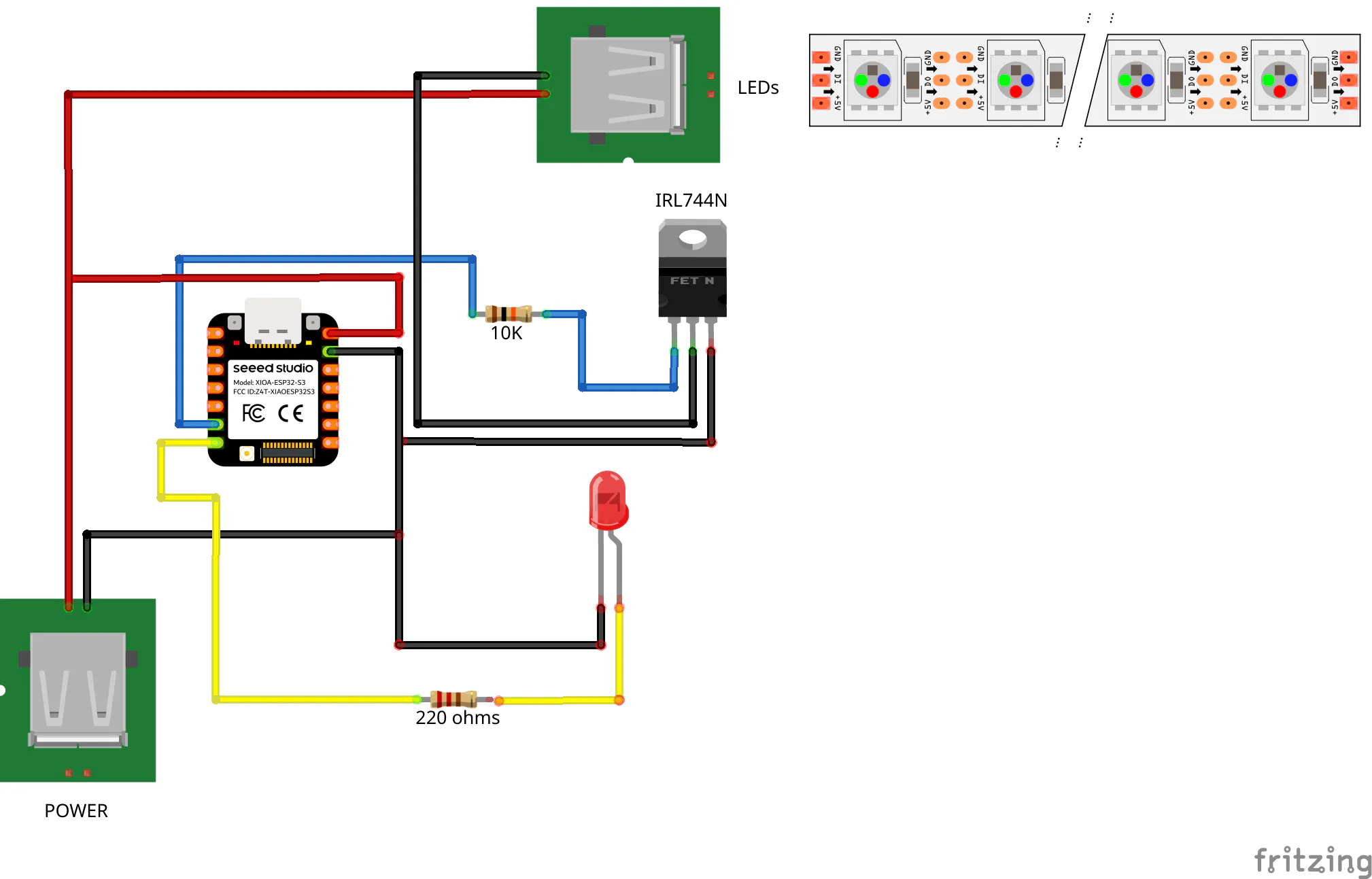
- ESP32 board (Seeed XIAO ESP32-S3 used in this project)
- IRLZ44N MOSFET
- 10k resistor
- 220 ohms resistor
- 5mm LED (color not important)
- 2x USB-A Pcb mount
- Powered via USB
- LED power is routed through the ESP32 5 V pin by design
- Common ground between ESP32 and LED strip
A custom 3D printed enclosure is used to:
- Hold the PCB securely
- Protect the electronics
- Provide cable strain relief
- Mount the assembly on the back of the printer
The schematic includes:
- ESP32 GPIO to MOSFET gate connection
- Gate pull-down resistor
- MOSFET low-side switching for the LED strip
- Shared ground reference
- Status LED output
The schematic files are included in the repository, in the PCB directory.
PCBA dedicated PCB was designed specifically for this project.
This is my third attempt at making a PCB, so bare with me. I know a lot of things could be done differently... and better.
You can get it directly from PCBWay.
FYI: I don't get anything from it, but they have sponsered it and I'm gratefull for it.
The PCB is not necessary for the project. Here's the schematic in Fritzing
And here's the first prototype:
To assemble it, just place the pieces in the right places - it's not hard and all the holes are identified 😄 !
Leave the LED for last - I'll explain later.
Before soldering the LED, measure the length of the legs so, when you place everything inside the 3D printed enclosure and close the LID, the LED stays a bit above the LID.
It's snap fit - you can remove it easily.
Now, place the LID.
IMPORTANT: When assembling the PCB into the 3D printed enclosure, check the labels near the USB-A PCB mounts.
The one labeled POWER is to the side where is the POWER Symbol and the one labeled To LEDS is to the side where the LED symbol is.
To connect to POWER, use the POWER symbol side and to the LEDs, use the LED Symbol side. :)
To secure it to the printer, use a magnetic strip glued to the enclosure.
CODEThe code hasn't much in need of change, just some configurations.
You need to know:
- Your Wi-Fi SSID and password (duh)
- Your printer IP address
- Your printer ACCESS_CODE (you can see this in the printer menus)
- your printer SERIAL (you can see this also in your printer menus)
First, you need to add your Wi-Fi credentials
// WiFi
const char* WIFI_SSID     = "";    // Your wifi network
const char* WIFI_PASSWORD = "";    // your wifi network password
The next information needed is from your printer.
- PRINTER_IP is the address of the printer on your network
- ACCESS_CODE you get it from the printer
- PRINTER_SERIAL is your printer serial number that you can also get from the menus of the printer.
// Bambu
const char* PRINTER_IP      = "xxx.xxx.xxx.xxx";  // Printer IP
const int   PRINTER_PORT    = 8883;    // No need to change - static
const char* PRINTER_USER    = "bblp";  // no change - static
const char* ACCESS_CODE     = "";      // LAN Access Code (From printer)
const char* PRINTER_SERIAL  = "";    // Serial number (From printer)
The following libraries are needed to install in the Arduino IDE
#include <WiFi.h>
#include <WiFiClientSecure.h>
#include <PubSubClient.h>
#include <ArduinoJson.h>
Here's it on my printer. I'm connected it to my Panda Branch


Comments