


Hardware components | ||||||
 |
| × | 1 | |||
| × | 1 | ||||
| × | 1 | ||||
Software apps and online services | ||||||
 |
| |||||
 |
| |||||
why use a separate remote control and buy batteries for them also it is hard for you to find each remote control at the time you could use only one little board fixed on a ring on your finger and control what ever you want with just one click from your finger or switch on / off any device you want
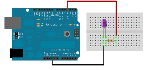
IR receiver
First thing you have to connect the IR receiver to any arduino board as shown in this schematic then upload the IR receiver code
after uploading the code point the remote control of your tv or dvd or whatever you want to the IR receiver and click the button you want to save in my case i will save the button increasing or decreasing the channel no.
watch the serial monitor you will see something like that
500 usec, 300 usec
the first no which is 500 describes the delay time when IR doesn't send anything while the 300 describes the time IR sends signal .
now we have the code of the button we want to use in our project

IR Transmitter
for the transmitter to work as required we have to upload the IR transmitter code to the arduino board after modifying SendChannelUpCode function by writing the IR on and off time in the code
replacing this :
delayMicroseconds();
pulseIR();
by values we read from IR receiver in the last step in my case were 500 usec, 300 usec:
delayMicroseconds(500);
pulseIR(300);
replacing this :
delayMicroseconds();
pulseIR();
by values we read from IR receiver in the last step in my case were 500 usec, 300 usec:
delayMicroseconds(500);
pulseIR(300);


_3u05Tpwasz.png?auto=compress%2Cformat&w=40&h=40&fit=fillmax&bg=fff&dpr=2)
Comments