

Learning about automation and motor control is a fundamental part of technical training in electricity and electromechanics. Having access to modern, safe, and versatile educational resources is essential for teachers and students to practice and experiment in the classroom.
In this article series, I’ll introduce you to an IoT educational module designed for hands-on practice with AC motor control (both single-phase and three-phase), using the StamPLC from M5Stack as the “brain.” This IoT programmable logic controller is not only easy to use and program, but also offers Wi-Fi connectivity and several built-in sensors, allowing you to go beyond traditional practices and explore remote monitoring and control functions.
If you’re new to the StamPLC, I recommend starting with my previous article where I cover its main features and capabilities: Discovering the StamPLC: Features and Functions
In this first part, you’ll get to know the educational module itself, the goals of the project, its main components, and how to perform initial tests using the pre-installed firmware on the StamPLC. In upcoming articles, we’ll go step by step through various motor control maneuvers—from basic to advanced—taking advantage of the connectivity and monitoring features this controller has to offer.
Educational Module for Motor ControlThe module presented in this series is designed to make it easy to practice, analyze, and experiment with single-phase and three-phase motor control in the classroom or lab. Its design allows students to safely interact with the most commonly used elements in industrial automation, combining traditional control logic with the new possibilities offered by IoT technology.
Main ComponentsThe module includes the following main elements, separated into control and power circuits:
Control Circuit:
- M5Stack StamPLC: The IoT programmable logic controller at the heart of the module, receiving signals, processing them, and triggering control outputs.
- 24 VDC Power Supply: Provides the necessary energy for the StamPLC and command devices.
- Two-pole circuit breaker: Protects against overcurrents in the power and control circuits.
- Indicator Lights: Show different operating conditions (running, error, etc.).
- Control Pushbuttons: For manual actions like start and stop.
Power Circuit:
- Three-phase Contactor: Controls turning the motor on and off.
- Thermal OverloadRelay: Provides overload protection, shutting down the system if dangerous conditions are detected.
- Three-phase Socket: Makes connecting the motor easier.
- Slotted WireDuct and Terminal Blocks: Organize and protect wiring, making review and learning simpler.
It’s worth noting that the components used here are the same ones you’ll typically find in everyday automation and control practices at technical schools. You might see parts from different brands or models, depending on what’s available in the lab. This setup is just a suggestion—feel free to adapt, add, or swap components based on your needs and available materials.
Power connectionsThe system has two separate power connections:
- On one side, single-phase AC (220V in my country) powers the 24 VDC supply and some command devices.
- On the other side, a separate connection provides power for the main circuit, which can be single-phase or three-phase.
This setup is very common in educational labs and workshops, clearly separating power and control circuits. This improves safety and makes learning easier.
Assembly and LayoutAll components are mounted using standard industrial techniques, like DIN rail mounting and slotted duct for neat wiring.This approach not only ensures safety and tidiness but also helps students get familiar with the standards they’ll find in real installations.
The layout makes it easy for students to identify each component and follow the wiring routes. The cabling is organized and channeled for maximum safety and clarity.
This kind of build also supports teamwork and collaborative learning, since students can observe and interact with the various devices under teacher supervision.
Educational Advantages- Safety: Enables real-world practice without exposing students to high-voltage hazards.
- Flexibility: Connections can be modified or new elements added for different exercises.
- Clear visualization: The open, organized design makes it easy to understand circuits and spot faults.
- IoT integration: The StamPLC makes it possible to experiment with remote monitoring, Wi-Fi control, and data collection via its internal sensors.
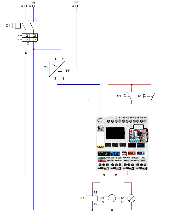
The circuit assembled in the educational module for the tests covered in this article can be seen in the image below:
Power Supply
As you can see, single-phase AC power (Line and Neutral) enters the double-pole circuit breaker (Q1), which provides overcurrent protection. The output of the breaker feeds the power supply (V1), which is also connected to the protective earth (PE) wire. AC power is also used to supply the loads connected to the PLC outputs, as we’ll see later.
The power supply delivers 24 volts DC and powers the PLC via a jack. Although the PLC can operate at lower voltages (from 6V to 36V), I chose 24V because it’s a standard value in automation circuits.
Inputs
For this article, I’m using only two of the eight PLC inputs. Input 1 is connected to a green NO (normally open) pushbutton (S1), and Input 2 is connected to a red NC (normally closed) pushbutton (S2).
The pushbuttons are also connected to the PLC’s positive voltage output (+), so when they are closed, they apply +24V to the inputs. To complete the optocoupler input circuit, the COM (C) terminal is connected to the negative.
Outputs
In this circuit, I use three of the four outputs. Each output is a relay with three contacts: COM (common), NO (normally open), and NC (normally closed). In all three cases, the Line wire enters at the COM contact so that, when the output is activated, COM and NO are connected, energizing the corresponding load.
Output 1 activates the contactor coil (K1), Output 2 powers the green indicator light (H1), and Output 3 powers the red indicator light (H2).
Setup and TestingOne of the great advantages of the StamPLC is that it comes with pre-installed firmware, allowing you to start testing and configuring the unit without needing to write any code. This greatly simplifies the first experiences with the module, letting you focus on getting to know the hardware, checking connections, and validating the operation of different elements before jumping into programming.
In the following sections, I’ll show you how to use these basic functions to check the module status and run your first tests:
SettingThis function allows you to configure several PLC parameters, such as:
- Modbus slave address
- Buzzer activation/deactivation
- Time zone for NTP synchronization
- Firmware version display
In this case, I simply made sure the buzzer was enabled and set the time zone (UTC-3 for my country).
The dashboard lets you monitor and view the real-time status of the inputs and outputs. In the image below, you can see the status of the pushbuttons at rest: Input 1 is inactive, and Input 2 is active because the pushbutton is normally closed.
At the top of the screen (next to the clock), you’ll also see two indicators: Wi-Fi connection status and EzData service status. We’ll look at how these work in more detail later.
Log MonitorThis diagnostic tool displays data received from internal sensors or communication ports.
The factory firmware on the StamPLC includes support for EzData, the M5Stack cloud platform. This integration allows you to easily store, visualize, and share data collected by the StamPLC, as well as control the relays and monitor input status remotely.
To access EzData services, you first need to configure the StamPLC’s Wi-Fi connection. In the EzData menu, select Setup WiFi Config; the StamPLC will enter setup mode and create a hotspot called M5StamPLC-WiFi-Config
Connect your phone to this network and scan the QR code shown on the screen (or go directly to 192.168.4.1). A page will appear where you enter your Wi-Fi network credentials.
Once Wi-Fi is set up, the StamPLC will connect automatically. To access it remotely, go to the EzData menu and select Monitor Link —this will show another QR code with the access URL.
After logging in (using your M5Stack account), you’ll see the input values and can control the relay outputs easily from anywhere.
In the Advanced section, you’ll find a list of URLs or endpoints that allow you to access internal sensor and input data, as well as control outputs remotely using the M5Stack API. This means you can query the PLC status and operate the relays from any other program, app, or even cloud service, opening up huge possibilities for integration and custom solutions.
Timer RelayThe Timer Relay function lets you activate and deactivate the different outputs at programmable intervals. It’s a handy way to test wiring and the operation of the relay outputs.
In the following video, you can see how I test each of the three outputs used in this circuit.
Trigger RelayThe Trigger Relay function lets you create basic logic by setting simple rules that link inputs to outputs. In the video below, I show how to set up a basic Start/Stop circuit to test both the pushbuttons and outputs. (Input 2 is activated by LOW because the pushbutton is normally closed.)
ConclusionsThe educational module presented in this article shows how it’s possible to bring safe, flexible, and industry-standard automation and motor control practices into the classroom. Thanks to the M5Stack StamPLC and its pre-installed firmware, we can carry out initial tests, validate wiring, and get familiar with the hardware without having to code from scratch. Using features like the Dashboard, Log Monitor, Timer Relay, and Trigger Relay, you can experiment with typical industry maneuvers, combining classic control logic with new IoT capabilities.
This overview of the educational module sets the stage for more advanced implementations, exploring the full potential of the StamPLC in various applications. In future articles, we’ll dive deeper into specific motor control sequences and real-world projects that make the most of this module.
f you have any questions or suggestions, feel free to leave them in the comment section below.
For more information and projects, you can check out my blog and social media.
See you next time! 🚀

Comments