

In this project, we’ll learn how to design and build a complete IoT-based control system using the PIC16F877A microcontroller.This project allows you to control electrical appliances wirelessly via Bluetooth — an ideal example of combining microcontroller programming, communication, and circuit design for smart home automation.
🧠 Project OverviewThis IoT-based Bluetooth Relay Control System uses the PIC16F877A microcontroller to receive commands from a Bluetooth module and control multiple relays connected to electrical loads.It’s a perfect embedded systems project for IoT learners, electronics students, and automation enthusiasts.
You’ll learn:
Bluetooth communication with PIC microcontroller
- Bluetooth communication with PIC microcontroller
Relay interfacing and switching logic
- Relay interfacing and switching logic
Circuit simulation and PCB design using Proteus
- Circuit simulation and PCB design using Proteus
Mobile app control via serial commands
- Mobile app control via serial commands
Below is the complete list of components used in this IoT project:
PIC16F877A Microcontroller (1 pc)
- PIC16F877A Microcontroller (1 pc)
Bluetooth Module HC-05 or HC-06 (1 pc)
- Bluetooth Module HC-05 or HC-06 (1 pc)
5V Relay Module (4 pcs)
- 5V Relay Module (4 pcs)
Transistor BC547 or TL917 (4 pcs)
- Transistor BC547 or TL917 (4 pcs)
Resistors 330Ω (4 pcs)
- Resistors 330Ω (4 pcs)
Resistors 10kΩ (4 pcs)
- Resistors 10kΩ (4 pcs)
LED Indicators (4 pcs)
- LED Indicators (4 pcs)
Diodes 1N4007 (4 pcs)
- Diodes 1N4007 (4 pcs)
Voltage Regulator IC 7805 (1 pc)
- Voltage Regulator IC 7805 (1 pc)
Electrolytic Capacitor 100µF (2 pcs)
- Electrolytic Capacitor 100µF (2 pcs)
Ceramic Capacitor 104pF (2 pcs)
- Ceramic Capacitor 104pF (2 pcs)
Crystal Oscillator 20MHz (1 pc)
- Crystal Oscillator 20MHz (1 pc)
22pF Capacitors (2 pcs)
- 22pF Capacitors (2 pcs)
Push Buttons / Switches (3 pcs)
- Push Buttons / Switches (3 pcs)
DC Power Jack (1 pc)
- DC Power Jack (1 pc)
Jumper Wires (as needed)
- Jumper Wires (as needed)
12V DC Power Supply (1 pc)
- 12V DC Power Supply (1 pc)
Custom PCB Board (1 pc)
- Custom PCB Board (1 pc)
Discover Easy, Affordable, and Reliable PCB manufacturing with JLCPCB!Register to get $70 New customer coupons:https://jlcpcb.com/?from=EST
Special Deal: Get a $30 coupon for JLCPCB premium 6-layer PCBs: https://jlcpcb.com/6-layer-pcb?from=getcoupon
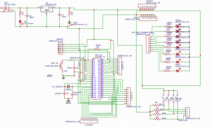
The circuit diagram (shown above) illustrates how the PIC16F877A communicates with the Bluetooth module and controls four relays through its PORTB pins.
Bluetooth Communication:The Bluetooth module is connected to the microcontroller via RC6 (TX) and RC7 (RX) pins for UART communication.
- Bluetooth Communication:The Bluetooth module is connected to the microcontroller via
RC6 (TX)andRC7 (RX)pins for UART communication.
Relay Control:Relays are connected to pins RB0, RB1, RB2, and RB3 using transistors as drivers. Each relay operates an LED indicator for visual feedback.
- Relay Control:Relays are connected to pins
RB0,RB1,RB2, andRB3using transistors as drivers. Each relay operates an LED indicator for visual feedback.
Power Supply:The circuit uses a 7805 voltage regulator to step down and stabilize the 5V supply for both the microcontroller and Bluetooth module.
- Power Supply:The circuit uses a 7805 voltage regulator to step down and stabilize the 5V supply for both the microcontroller and Bluetooth module.
Here’s the C code used to control the relays via Bluetooth commands. The code is written in MPLAB X IDE using the XC8 compiler.
#include <16f877a.h>
#fuses HS, NOWDT, NOPROTECT, NOLVP
#use delay(clock=20000000)
#use rs232(baud=9600, xmit=PIN_C6, rcv=PIN_C7)

#define RELAY1 PIN_B0
#define RELAY2 PIN_B1
#define RELAY3 PIN_B2
#define RELAY4 PIN_B3

void main() {
    char data;
    set_tris_b(0xF0); // RB0–RB3 as output

    while(TRUE) {
        if(kbhit()) {
            data = getc();
            switch(data) {
                case '1': output_high(RELAY1); break;
                case '2': output_low(RELAY1); break;
                case '3': output_high(RELAY2); break;
                case '4': output_low(RELAY2); break;
                case '5': output_high(RELAY3); break;
                case '6': output_low(RELAY3); break;
                case '7': output_high(RELAY4); break;
                case '8': output_low(RELAY4); break;
                default: break;
            }
        }
    }
}
📘 Code Description:The program reads Bluetooth data using UART communication.
- The program reads Bluetooth data using UART communication.
Each received character (‘1’–‘8’) triggers a corresponding relay ON/OFF action.
- Each received character (‘1’–‘8’) triggers a corresponding relay ON/OFF action.
Four relays are controlled through PORTB pins RB0–RB3.
- Four relays are controlled through PORTB pins RB0–RB3.
The PCB layout, designed in Proteus ARES, integrates all components neatly on a single board.
Features of the PCB Design:
Four relay control circuits with flyback diodes
- Four relay control circuits with flyback diodes
On-board Bluetooth interface
- On-board Bluetooth interface
7805 regulator power supply section
- 7805 regulator power supply section
LED status indicators
- LED status indicators
12V DC input with polarity protection
- 12V DC input with polarity protection
Clearly labeled connectors and ports
- Clearly labeled connectors and ports
This compact PCB ensures durability, professional look, and ease of assembly for IoT and automation projects.
📱 Mobile App IntegrationTo control the system, connect your smartphone to the Bluetooth module (HC-05/06).Use any Bluetooth Terminal App or Arduino Bluetooth Controller to send commands like:
1 → Turn ON Relay 1
2 → Turn OFF Relay 1
3 → Turn ON Relay 2
4 → Turn OFF Relay 2
5 → Turn ON Relay 3
6 → Turn OFF Relay 3
7 → Turn ON Relay 4
8 → Turn OFF Relay 4
🎯Video ReferenceDiscover Easy, Affordable, and Reliable PCB manufacturing with JLCPCB!Register to get $70 New customer coupons:https://jlcpcb.com/?from=EST
Special Deal: Get a $30 coupon for JLCPCB premium 6-layer PCBs: https://jlcpcb.com/6-layer-pcb?from=getcoupon
🚀 Applications✅ Smart Home Automation✅ IoT-Based Device Control✅ Industrial Load Switching✅ Smart Energy Systems✅ Embedded Systems Training Projects
🎯 ConclusionYou’ve now learned how to create a Bluetooth-controlled IoT project using PIC16F877A — from coding and circuit design to PCB layout and wireless control.This project demonstrates the true power of microcontrollers in IoT automation, and you can easily upgrade it with Wi-Fi (ESP8266), sensors, or mobile app dashboards for more advanced applications.


Comments