

Do you want to automatically power a 12V fan using both AC and DC power? This DIY project is perfect for inverter systems, battery backup setups, and cooling applications. In this tutorial, I will demonstrate how to create a 12V AC/DC fan system that intelligently switches between mains power and a 12V battery using a smart circuit and a few electronic components.
🌟 Features✅ Automatically uses AC power when available.
- ✅ Automatically uses AC power when available.
✅ Automatically switches to battery backup when AC is off.
- ✅ Automatically switches to battery backup when AC is off.
✅ Includes buck converter, LED indicator, and fan control.
- ✅ Includes buck converter, LED indicator, and fan control.
✅ Ideal for battery packs, solar systems, and DC appliances.
- ✅ Ideal for battery packs, solar systems, and DC appliances.
Discover Easy, Affordable, and Reliable PCB manufacturing with JLCPCB!Register to get $70 New customer coupons:https://jlcpcb.com/?from=EST Special Deal: Get a $30 coupon for JLCPCB premium 6-layer PCBs: https://jlcpcb.com/6-layer-pcb?from=getcoupon
🧰 C omponent List (Line by Line)LM2596 Buck Converter Module – 1 pc
- LM2596 Buck Converter Module – 1 pc
1N5822 Schottky Diode – 3 pcs (D5, D6, D8)
- 1N5822 Schottky Diode – 3 pcs (D5, D6, D8)
1N5819 Diode – 1 pc (D3)
- 1N5819 Diode – 1 pc (D3)
1N5408 High-Current Diode – 2 pcs (D1, D2)
- 1N5408 High-Current Diode – 2 pcs (D1, D2)
LED (Red) – 1 pc (for power indication)
- LED (Red) – 1 pc (for power indication)
1kΩ Resistor – 1 pc (for LED current limiting)
- 1kΩ Resistor – 1 pc (for LED current limiting)
10kΩ Resistor – 1 pc (MOSFET gate pull-down)
- 10kΩ Resistor – 1 pc (MOSFET gate pull-down)
IRF9540N P-Channel MOSFET – 1 pc
- IRF9540N P-Channel MOSFET – 1 pc
880μH Inductor – 1 pc
- 880μH Inductor – 1 pc
220μF Capacitor (Electrolytic) – 2 pcs (C1, C2)
- 220μF Capacitor (Electrolytic) – 2 pcs (C1, C2)
Switch (SPST or jumper type) – 1 pc (manual control)
- Switch (SPST or jumper type) – 1 pc (manual control)
12V DC Fan (2-pin or 3-pin) – 1 pc
- 12V DC Fan (2-pin or 3-pin) – 1 pc
Battery (12V Lead-Acid or Li-ion pack) – 1 pc
- Battery (12V Lead-Acid or Li-ion pack) – 1 pc
Terminal Block (2-pin or 3-pin) – As needed for AC input, battery, and load
- Terminal Block (2-pin or 3-pin) – As needed for AC input, battery, and load
Wires (AWG 20 or thicker) – As needed
- Wires (AWG 20 or thicker) – As needed
PCB or Perfboard – 1 pc (for assembly, optional)
- PCB or Perfboard – 1 pc (for assembly, optional)
Heatsink (for LM2596 if needed) – Optional
- Heatsink (for LM2596 if needed) – Optional
Soldering Iron and Solder – For connections
- Soldering Iron and Solder – For connections
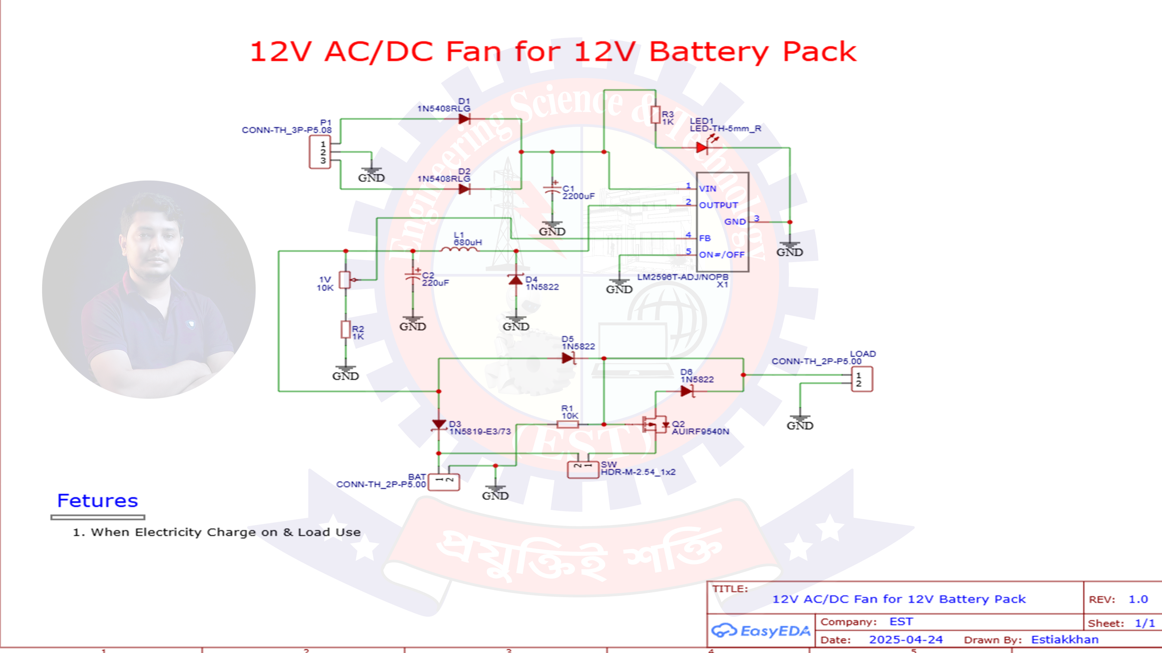
D1 & D2 (1N5408): These diodes form a rectifier to allow AC to be safely converted to DC.
- D1 & D2 (1N5408): These diodes form a rectifier to allow AC to be safely converted to DC.
C1 (220μF): Smooths out the ripples from the rectified voltage.
- C1 (220μF): Smooths out the ripples from the rectified voltage.
LED1 + R3: Indicates AC power is ON.
- LED1 + R3: Indicates AC power is ON.
LM2596 Buck Converter (X1):
Converts high DC voltage (from rectified AC) down to a stable 12V.
- Converts high DC voltage (from rectified AC) down to a stable 12V.
Pinout:
VIN: Input Voltage
- VIN: Input Voltage
GND: Ground
- GND: Ground
OUTPUT: Regulated 12V Output
- OUTPUT: Regulated 12V Output
ON/OFF & FB: Control and Feedback pins for operation
- ON/OFF & FB: Control and Feedback pins for operation
- Pinout:VIN: Input VoltageGND: GroundOUTPUT: Regulated 12V OutputON/OFF & FB: Control and Feedback pins for operation
- LM2596 Buck Converter (X1):Converts high DC voltage (from rectified AC) down to a stable 12V.Pinout:VIN: Input VoltageGND: GroundOUTPUT: Regulated 12V OutputON/OFF & FB: Control and Feedback pins for operation
D5 (1N5822): Allows current flow from the buck converter to the fan only when AC is present.
- D5 (1N5822): Allows current flow from the buck converter to the fan only when AC is present.
D3 (1N5819): Prevents backflow from the battery when AC is ON.
- D3 (1N5819): Prevents backflow from the battery when AC is ON.
D6 (1N5822): Ensures one-way flow from battery to the MOSFET gate.
- D6 (1N5822): Ensures one-way flow from battery to the MOSFET gate.
Q2 (IRF9540N P-Channel MOSFET):
Acts as an electronic switch to allow battery power to the fan when AC is off.
- Acts as an electronic switch to allow battery power to the fan when AC is off.
Gate Control:
R1 (10kΩ) pulls the gate high to keep the MOSFET OFF when not triggered.
- R1 (10kΩ) pulls the gate high to keep the MOSFET OFF when not triggered.
When AC is off, the gate is pulled LOW via D6, turning the MOSFET ON.
- When AC is off, the gate is pulled LOW via D6, turning the MOSFET ON.
- Gate Control:R1 (10kΩ) pulls the gate high to keep the MOSFET OFF when not triggered.When AC is off, the gate is pulled LOW via D6, turning the MOSFET ON.
- Q2 (IRF9540N P-Channel MOSFET):Acts as an electronic switch to allow battery power to the fan when AC is off.Gate Control:R1 (10kΩ) pulls the gate high to keep the MOSFET OFF when not triggered.When AC is off, the gate is pulled LOW via D6, turning the MOSFET ON.
Fan Output is connected to the drain of the MOSFET and receives power either from:
AC Source (via Buck Converter and D5) when AC is available
- AC Source (via Buck Converter and D5) when AC is available
Battery (via D8 and MOSFET Q2) when AC is not available
- Battery (via D8 and MOSFET Q2) when AC is not available
- Fan Output is connected to the drain of the MOSFET and receives power either from:AC Source (via Buck Converter and D5) when AC is availableBattery (via D8 and MOSFET Q2) when AC is not available
Double-check diode polarity.
- Double-check diode polarity.
Use heatsinks on the LM2596 if the fan draws high current.
- Use heatsinks on the LM2596 if the fan draws high current.
Test the output using a multimeter before connecting the fan.
- Test the output using a multimeter before connecting the fan.
Discover Easy, Affordable, and Reliable PCB manufacturing with JLCPCB!Register to get $70 New customer coupons:https://jlcpcb.com/?from=EST Special Deal: Get a $30 coupon for JLCPCB premium 6-layer PCBs: https://jlcpcb.com/6-layer-pcb?from=getcoupon
🔺 Final ThoughtsThis project is a must-have for any DIY enthusiast working on battery systems or off-grid setups. With just a few inexpensive components, you can create a smart 12V AC/DC fan system that’s perfect for inverters, solar systems, or any power backup configuration.
If you liked this tutorial, please vote, like, and share it!


Comments