

A Pure Sine Wave Inverter is a must-have for any serious off-grid or backup power system. Unlike modified or square wave inverters, it delivers a clean, sinusoidal AC output identical to the grid, making it ideal for sensitive electronics, medical equipment, and precision appliances.
In this guide, we'll walk you through:
The basic fundamentals of converting DC to Pure Sine Wave AC.
- The basic fundamentals of converting DC to Pure Sine Wave AC.
The role of the EGS002 module.
- The role of the EGS002 module.
Detailed explanation of the circuit diagram.
- Detailed explanation of the circuit diagram.
How to use a UPS Transformer.
- How to use a UPS Transformer.
By the end, you’ll understand exactly how to build a Pure Sine Wave Inverter using the popular EGS002 module.
⚡️ Fundamentals of Pure Sine Wave InverterA Pure Sine Wave Inverter works in five steps:
Input Source: A low-voltage DC supply (12V/24V).
- Input Source: A low-voltage DC supply (12V/24V).
Wave Generation: The EGS002 SPWM (Sinusoidal Pulse Width Modulation) module generates PWM signals.
- Wave Generation: The EGS002 SPWM (Sinusoidal Pulse Width Modulation) module generates PWM signals.
Switching Circuit: MOSFETs or IGBTs, arranged in an H-Bridge configuration, chop the DC voltage into a high-frequency SPWM signal.
- Switching Circuit: MOSFETs or IGBTs, arranged in an H-Bridge configuration, chop the DC voltage into a high-frequency SPWM signal.
Transformer Action: The SPWM signal is stepped up by a UPS transformer (e.g., 12V–230V).
- Transformer Action: The SPWM signal is stepped up by a UPS transformer (e.g., 12V–230V).
Filtering: An LC filter cleans the signal, yielding a smooth 230V Pure Sine Wave Output.
- Filtering: An LC filter cleans the signal, yielding a smooth 230V Pure Sine Wave Output.
The EGS002 is a dedicated Pure Sine Wave Inverter Driver Board that:
Provides SPWM wave generation.
- Provides SPWM wave generation.
Includes overload, over-voltage, under-voltage, and temperature protection.
- Includes overload, over-voltage, under-voltage, and temperature protection.
Provides feedback for regulating the output voltage.
- Provides feedback for regulating the output voltage.
Why Use the EGS002?✅ Simplifies design for Pure Sine Wave Inverters.✅ Works reliably for 50 Hz or 60 Hz output.✅ Provides built-in protection and adjustable settings.
⚡️ Circuit Diagram ExplainedDiscover Easy, Affordable, and Reliable PCB manufacturing with JLCPCB!Register to get $70 New customer coupons:https://jlcpcb.com/?from=EST
Special Deal: Get a $30 coupon for JLCPCB premium 6-layer PCBs: https://jlcpcb.com/6-layer-pcb?from=getcoupon
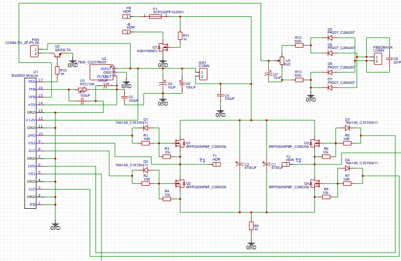
Refer to the images you shared for thePCB layout and schematic. Here’s the breakdown:
Input Section (12V/24V):
The inverter uses a battery connected to the PCB.
- The inverter uses a battery connected to the PCB.
The input capacitor bank (C1, C2) smoothens the DC.
- The input capacitor bank (C1, C2) smoothens the DC.
- Input Section (12V/24V):The inverter uses a battery connected to the PCB.The input capacitor bank (C1, C2) smoothens the DC.
EGS002 Control Board (U1):
Provides SPWM signals (HI and LO outputs).
- Provides SPWM signals (HI and LO outputs).
Connected to MOSFET gates via gate resistors (R1–R8).
- Connected to MOSFET gates via gate resistors (R1–R8).
- EGS002 Control Board (U1):Provides SPWM signals (HI and LO outputs).Connected to MOSFET gates via gate resistors (R1–R8).
MOSFET Power Stage (Q1–Q4):
MOSFETs alternately switch ON and OFF based on SPWM signals.
- MOSFETs alternately switch ON and OFF based on SPWM signals.
This creates the high-frequency SPWM needed for the sine wave.
- This creates the high-frequency SPWM needed for the sine wave.
- MOSFET Power Stage (Q1–Q4):MOSFETs alternately switch ON and OFF based on SPWM signals.This creates the high-frequency SPWM needed for the sine wave.
Driver Circuitry:
Gate drivers (Q5, Q7), resistors, and diodes shape the gate drive signals for clean MOSFET switching.
- Gate drivers (Q5, Q7), resistors, and diodes shape the gate drive signals for clean MOSFET switching.
- Driver Circuitry:Gate drivers (Q5, Q7), resistors, and diodes shape the gate drive signals for clean MOSFET switching.
Transformer (T1 / T2):
The SPWM signal is stepped up from 12V to 230V (or your target voltage).
- The SPWM signal is stepped up from 12V to 230V (or your target voltage).
The center-tapped design allows generation of both halves of the AC wave.
- The center-tapped design allows generation of both halves of the AC wave.
- Transformer (T1 / T2):The SPWM signal is stepped up from 12V to 230V (or your target voltage).The center-tapped design allows generation of both halves of the AC wave.
Feedback & Protection:
The feedback loop ensures stable output voltage.
- The feedback loop ensures stable output voltage.
The EGS002 monitors output voltage and adjusts PWM accordingly.
- The EGS002 monitors output voltage and adjusts PWM accordingly.
Fuses and protection diodes (D1–D5) prevent damage from surges or reverse connections.
- Fuses and protection diodes (D1–D5) prevent damage from surges or reverse connections.
- Feedback & Protection:The feedback loop ensures stable output voltage.The EGS002 monitors output voltage and adjusts PWM accordingly.Fuses and protection diodes (D1–D5) prevent damage from surges or reverse connections.
✅ Pure, clean output for sensitive electronics.✅ High efficiency and reliability.✅ Ability to drive motors, TVs, and medical equipment reliably.✅ Protection features for over-voltage, over-current, and thermal overload.
⚡️ Key ComponentsHere are the core parts used:
EGS002 SPWM Controller: The brain of the inverter.
- EGS002 SPWM Controller: The brain of the inverter.
MOSFETs (e.g., IRF3205): High-power switching devices.
- MOSFETs (e.g., IRF3205): High-power switching devices.
UPS Transformer: Provides voltage step-up and isolation.
- UPS Transformer: Provides voltage step-up and isolation.
Gate Resistors & Diodes: Protect MOSFET gates.
- Gate Resistors & Diodes: Protect MOSFET gates.
Filter Circuit (LC): Smoothens the output.
- Filter Circuit (LC): Smoothens the output.
Capacitors & Fuses: Provides stability and safety.
- Capacitors & Fuses: Provides stability and safety.
Discover Easy, Affordable, and Reliable PCB manufacturing with JLCPCB!Register to get $70 New customer coupons:https://jlcpcb.com/?from=EST
Special Deal: Get a $30 coupon for JLCPCB premium 6-layer PCBs: https://jlcpcb.com/6-layer-pcb?from=getcoupon
⚡️ Final OutputThe result is a stable, clean 230V AC Pure Sine Wave Output that can run any equipment at its rated efficiency and reliability.
⚡️ ApplicationsHome and office backup systems.
- Home and office backup systems.
Off-grid solar setups.
- Off-grid solar setups.
Medical equipment and sensitive electronics.
- Medical equipment and sensitive electronics.
Motor-driven appliances.
- Motor-driven appliances.
Building a Pure Sine Wave Inverter with the EGS002 module and a UPS Transformer is one of the best ways to achieve a clean, stable AC output from a DC supply. This design delivers performance that rivals expensive commercial units and can be tailored for specific needs.


Comments