

Have you ever wished your DC load (like a WiFi Router, LED Light, CCTV Camera, or small DC Fan) could keep running even when the main power supply goes off? In this project, I’ll show you how to make a DC Changeover Circuit using a simple relay and diodes, which automatically switches between a DC adapter and a battery backup without interruption.
This DIY DC Changeover is very useful for UPS systems, routers, LED lights, CCTV, Arduino projects, and small electronics. The best part is: you can build it easily at home with just a few components!
⚡ Features of This DIY DC ChangeoverAutomatic switching between DC adapter and battery backup.
- Automatic switching between DC adapter and battery backup.
Protects battery from reverse current.
- Protects battery from reverse current.
Works with 12V adapters and 12V lead-acid/LiFePO4 batteries.
- Works with 12V adapters and 12V lead-acid/LiFePO4 batteries.
Low-cost and reliable circuit.
- Low-cost and reliable circuit.
Ideal for WiFi router UPS, CCTV backup, and DIY power systems.
- Ideal for WiFi router UPS, CCTV backup, and DIY power systems.
Here’s the components list (step by step) used in the attached circuit diagram:
DC Power Jack (Input: 12V DC Adapter)
- DC Power Jack (Input: 12V DC Adapter)
Battery Connector (12V Battery)
- Battery Connector (12V Battery)
Relay (SPST 12V)
- Relay (SPST 12V)
Diode 1N5822 (Schottky Diode for low drop)
- Diode 1N5822 (Schottky Diode for low drop)
Diode 1N4007 x 2 (General purpose rectifier diodes)
- Diode 1N4007 x 2 (General purpose rectifier diodes)
Capacitors 1000µF x 2 (For filtering and smooth switching)
- Capacitors 1000µF x 2 (For filtering and smooth switching)
Load Connector (Output: WiFi Router / Fan / LED Light / CCTV, etc.)
- Load Connector (Output: WiFi Router / Fan / LED Light / CCTV, etc.)
Discover Easy, Affordable, and Reliable PCB manufacturing with JLCPCB!Register to get $70 New customer coupons:https://jlcpcb.com/?from=EST
Special Deal: Get a $30 coupon for JLCPCB premium 6-layer PCBs: https://jlcpcb.com/6-layer-pcb?from=getcoupon
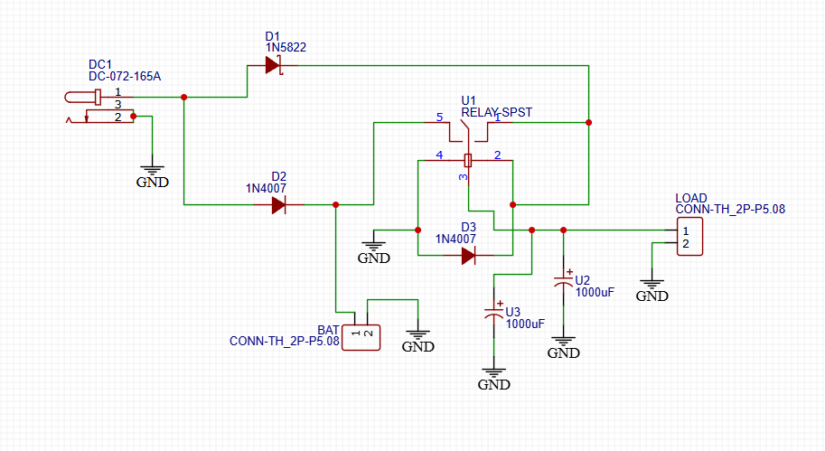
The DC Adapter (12V) is connected through a Schottky diode (D1 - 1N5822), which provides power to the load and prevents reverse current from the battery.
- The DC Adapter (12V) is connected through a Schottky diode (D1 - 1N5822), which provides power to the load and prevents reverse current from the battery.
The Battery (12V) is connected via D2 (1N4007), which only powers the load when the adapter supply fails.
- The Battery (12V) is connected via D2 (1N4007), which only powers the load when the adapter supply fails.
A Relay (SPST) is used to control the changeover between Adapter and Battery supply.
- A Relay (SPST) is used to control the changeover between Adapter and Battery supply.
D3 (1N4007) is placed across the relay coil to prevent back EMF damage.
- D3 (1N4007) is placed across the relay coil to prevent back EMF damage.
Two 1000µF capacitors (U2, U3) are connected across the load to smooth out voltage fluctuations and ensure stable output.
- Two 1000µF capacitors (U2, U3) are connected across the load to smooth out voltage fluctuations and ensure stable output.
When the adapter is present, the relay energizes and directly powers the load.
- When the adapter is present, the relay energizes and directly powers the load.
When the adapter fails, the relay de-energizes and automatically switches to battery supply without manual operation.
- When the adapter fails, the relay de-energizes and automatically switches to battery supply without manual operation.
This ensures seamless switching between Adapter → Battery → Load.
🔧 Step-by-Step InstructionsDiscover Easy, Affordable, and Reliable PCB manufacturing with JLCPCB!Register to get $70 New customer coupons:https://jlcpcb.com/?from=EST
Special Deal: Get a $30 coupon for JLCPCB premium 6-layer PCBs: https://jlcpcb.com/6-layer-pcb?from=getcoupon
Step 1: Assemble ComponentsGather all components listed above. Make sure you use a 12V relay matching your adapter and battery voltage.
Step 2: Place the RelayMount the relay on a PCB or breadboard. Connect the coil pins (85 & 86) to the adapter supply.
Step 3: Connect the DiodesConnect D1 (1N5822) from Adapter + to Load.
- Connect D1 (1N5822) from Adapter + to Load.
Connect D2 (1N4007) from Battery + to Load.
- Connect D2 (1N4007) from Battery + to Load.
Connect D3 (1N4007) across relay coil for protection.
- Connect D3 (1N4007) across relay coil for protection.
Solder 1000µF capacitors across Load + and GND to reduce voltage drops during switching.
Step 5: Connect the LoadFinally, connect your DC load (WiFi Router, Fan, or Light) to the load output connector.
Step 6: Test the CircuitFirst, power the adapter → Load should work directly.
- First, power the adapter → Load should work directly.
Remove adapter → Load should automatically switch to battery backup without turning off.
- Remove adapter → Load should automatically switch to battery backup without turning off.
WiFi Router UPS (never lose internet during power cuts)
- WiFi Router UPS (never lose internet during power cuts)
CCTV Backup
- CCTV Backup
Arduino/Raspberry Pi Projects
- Arduino/Raspberry Pi Projects
12V DC Lights & Fans
- 12V DC Lights & Fans
Portable Power Systems
- Portable Power Systems
Discover Easy, Affordable, and Reliable PCB manufacturing with JLCPCB!Register to get $70 New customer coupons:https://jlcpcb.com/?from=EST
Special Deal: Get a $30 coupon for JLCPCB premium 6-layer PCBs: https://jlcpcb.com/6-layer-pcb?from=getcoupon
📝 ConclusionThis DIY DC Changeover Circuit is a low-cost and effective solution for ensuring that your DC devices never lose power during electricity cuts. By using just a relay, diodes, and capacitors, you can make your own WiFi Router UPS, CCTV Backup, or DC Power Supply.


Comments