

In today’s solar-powered setups, especially for WiFi routers, modems, and small DC appliances, one major challenge is auto switching between solar and battery power during cloudy weather or at night. This DIY Mini DC IPS Auto Changeover Device solves that perfectly – simple, reliable, and fully automatic.
Let’s build it step-by-step!
Discover Easy, Affordable, and Reliable PCB manufacturing with JLCPCB!Register to get $70 New customer coupons:https://jlcpcb.com/?from=EST
Special Deal: Get a $30 coupon for JLCPCB premium 6-layer PCBs: https://jlcpcb.com/6-layer-pcb?from=getcoupon
🧠 What is a DC Auto Changeover System?A DC changeover circuit automatically switches power from the primary (solar or adapter) to a backup (battery) when the primary source fails or drops below a threshold. It is:
🔄 Automatic (No manual switching)
- 🔄 Automatic (No manual switching)
⚡ Fast (Relay-based instantaneous response)
- ⚡ Fast (Relay-based instantaneous response)
🔋 Safe (Protects battery and load)
- 🔋 Safe (Protects battery and load)
✅ WiFi Router & ONU Backup✅ Solar LED Light Systems✅ DC Fans and Mini Coolers✅ Home Security IP Cameras✅ Small IoT Devices
🔌 System Inputs & OutputsPort
- Function IN
- DC power (from Solar/Adapter) BAT
- 12V Battery input (backup) NO
- Load runs on solar if available NC
- Load switches here on solar failure
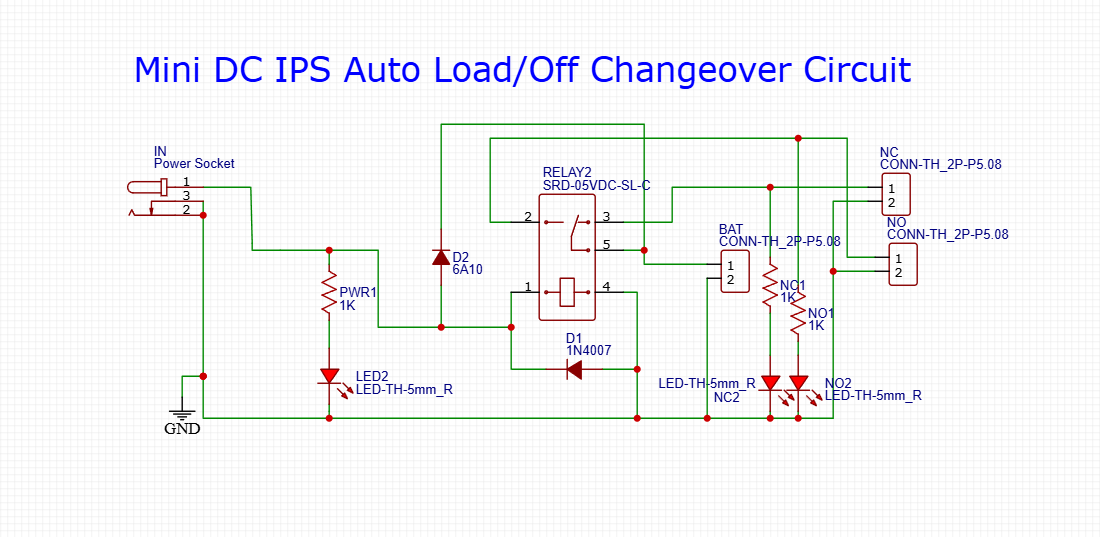
Relay Coil is powered by solar (IN).
- Relay Coil is powered by solar (IN).
If IN is present → relay pulls → NO contact closes (solar to load).
- If IN is present → relay pulls → NO contact closes (solar to load).
If IN fails → relay drops → NC contact closes (battery to load).
- If IN fails → relay drops → NC contact closes (battery to load).
D2 (6A10): Blocks backflow from battery to solar.
- D2 (6A10): Blocks backflow from battery to solar.
D1 (1N4007): Flyback diode across the relay to protect against voltage spikes.
- D1 (1N4007): Flyback diode across the relay to protect against voltage spikes.
LED2 (PWR), NO2, NC2: Show power status for IN, NO, and NC paths.
- LED2 (PWR), NO2, NC2: Show power status for IN, NO, and NC paths.
Resistors (1K): Limit current to LEDs.
- Resistors (1K): Limit current to LEDs.
Relay: SRD-05VDC-SL-C (5V coil)
- Relay: SRD-05VDC-SL-C (5V coil)
Diodes: 6A10 (D2), 1N4007 (D1)
- Diodes: 6A10 (D2), 1N4007 (D1)
Resistors: 1KΩ × 3 (PWR1, NC1, NO1)
- Resistors: 1KΩ × 3 (PWR1, NC1, NO1)
LED indicators: 3 pcs (PWR, NC2, NO2)
- LED indicators: 3 pcs (PWR, NC2, NO2)
Screw terminals (IN, BAT, NO, NC)
- Screw terminals (IN, BAT, NO, NC)
Female DC socket for solar input
- Female DC socket for solar input
📷 📷
This shows how each component connects and works together. The relay toggles the output path based on input power availability.
🖥 PCB Design & Layout
📷 Well-routed single-side PCB for compact and low-cost DIY
Discover Easy, Affordable, and Reliable PCB manufacturing with JLCPCB!Register to get $70 New customer coupons:https://jlcpcb.com/?from=EST
Special Deal: Get a $30 coupon for JLCPCB premium 6-layer PCBs: https://jlcpcb.com/6-layer-pcb?from=getcoupo
This model gives a real-life view of the assembled circuit board. You can easily solder this on a general-purpose PCB or fabricate this board using services like JLCPCB or EasyEDA.
⚙️ How to AssembleStart by placing and soldering resistors and diodes.
- Start by placing and soldering resistors and diodes.
Mount the relay and terminal blocks.
- Mount the relay and terminal blocks.
Solder the LEDs (match polarity: long leg = +).
- Solder the LEDs (match polarity: long leg = +).
Finally, solder the DC socket and test input with a power source.
- Finally, solder the DC socket and test input with a power source.
Use a multimeter to confirm relay switching and voltage at NO/NC terminals.
- Use a multimeter to confirm relay switching and voltage at NO/NC terminals.
Connect solar output or DC adapter to IN.
- Connect solar output or DC adapter to
IN.
Connect a fully charged 12V battery to BAT.
- Connect a fully charged 12V battery to
BAT.
Connect your load (router, etc.) across NO and GND terminals.
- Connect your load (router, etc.) across NO and GND terminals.
Done! The system now runs automatically.
- Done! The system now runs automatically.
Condition
Output
LED Status
Solar ON
Output from NO
NO2 = ON, NC2 = OFF
Solar OFF
Output from NC
NO2 = OFF, NC2 = ON
This auto switch is seamless and ensures that your connected load never shuts off.
📁 Download Resources🔗 Gerber Files – PCB Download
- 🔗 Gerber Files – PCB Download
🔗 PDF Circuit Schematic
- 🔗 PDF Circuit Schematic
🔗 Component Placement Diagram
- 🔗 Component Placement Diagram
Discover Easy, Affordable, and Reliable PCB manufacturing with JLCPCB!Register to get $70 New customer coupons: https://jlcpcb.com/?from=EST
Special Deal: Get a $30 coupon for JLCPCB premium 6-layer PCBs: https://jlcpcb.com/6-layer-pcb?from=getcoupon
🎥 We’re making a step-by-step Bangla YouTube tutorial on this project. Stay tuned on our channel: EST Experiments👉 Don’t forget to Subscribe and turn on notifications!
✅ Final ThoughtsThis DIY Solar Changeover Circuit is a must-have for every solar-powered home setup. It saves time, ensures reliability, and protects your router or smart home devices during power outages.

Comments