


I started work on this project by creating a test bed where I configured the analog inputs and outputs of the system and tested it using potentiometers in the place of flex sensors.
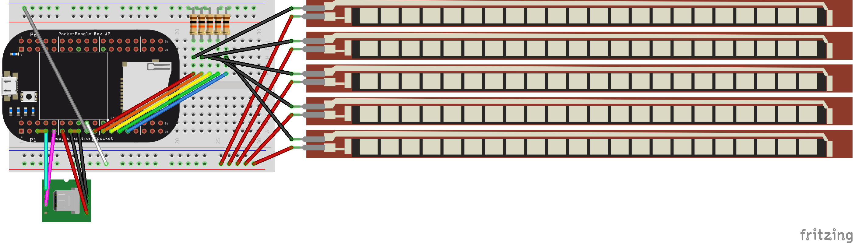
Each potentiometer was connected to a common ground and power supply, and each signal pin was connected to a different analog input. I created a simple program to print out the signal readings from each of the five inputs, which correspond to each of the five fingers of the glove. Upon final assembly of the glove, I re-made the same circuit on a small breadboard, and the schematic is included on this page. To configure the circuit to test with potentiometers, simply replace the first and second pins of the flex sensors with the first and second pins of five 10k potentiometers.
IntegratingAudio
While I was waiting for parts to come in, I was able to get the audio for the project fully functional. At first, I was considering using pulse width modulation for the project and creating a kind of synthesizer from a 3.5mm headphone jack, but I realized that this would rely on a really accurate reading out of the bend sensors. Also, the glove would be limited to five controls for each of the five fingers. I decided to create a drum kit instead because each finger bend could be used to trigger a sound, and I could learn more about how to process audio files in Linux. I was given a USB audio dongle for the PocketBeagle to help accomplish this. To connect the dongle, I soldered the VB and VI pins of the USB1 port on the PocketBeagle together, as well as the ID and GND pins. I connected a microUSB adapter to the correct USB1 port pins, connected a microUSB to USB adapter, and finally attached the dongle. At this point, I could plug in my headphones to establish a sound device that could be registered in Linux. Here is a really excellent video tutorial on how to set up your USB dongle as an audio device:
Flite is a basic text-to-speech program used in the tutorial that uses the audio driver we need to play sound files. If you've set up the drivers correctly and install flite, it should be able to play basic sentences. This serves as a good test to make sure everything is set up correctly on the audio end. A great written tutorial can also be found at this website.
At this point, I began to look for sound files to use for the instrument. I decided to create a drum kit, but any.wav recordings will work for the instrument sounds. Feel free to use the sounds I did, or create your own instrument! One of the awesome parts about this glove is that you can go back and change the sounds it makes. The sounds I used (Hand Clap, Bass Drum, Snare, Tom, 808) are from freesound.org, which has many .wav files that are listed under Creative Commons licenses. The ones I used are in my Github repository.
After downloading the files you want to use, put them somewhere in the PocketBeagle's file directory and note the location -- we'll need to direct to the audio player to the files using the full file path. To play the audio files, simply use the ALSA player command:
aplay <insert file path here>It should play through the headphones. If the volume is too high or too low, you can use "alsamixer" to change it.
Next, I modified the test bench program to play a sound for each potentiometer when it is turned more than halfway. I ran this program on the test setup and the program indeed played the audio files for each "finger" as soon as the knob turned from one side to the other (but not in both directions) To play the audio files in Python, you can just use "import os" to play it through the terminal:
import os
os.system("aplay <insert full file path here>")
Apart from setting up the PocketBeagle to start the program on boot, this essentially completes the software for the project. After the glove was built, I had to go back and tune the signal level that triggers a sound based on my flex sensors and glove, but that was it. On to the glove!
Creating the Velostat Flex SensorsTo get a basic idea of how to create the flex sensors using Velostat, I discovered the following video:
This video shows an extremely simplified process to create a basic flex sensor using conductive thread. I ran through this process once before starting to make improvements on the design so that it would be optimal for the glove. One necessary change I needed to make for the glove was folding the thread and taping it back over the top of the sensor to have both leads on the same end of the sensor.
Another big challenge with these sensors was to connect the stainless steel thread to wires that could be put into the PocketBeagle. They cannot be soldered, so I developed a method of crimping the thread into female pin connectors and smothering the entire base with a healthy amount of hot glue to establish a more durable connection.
After some minor trial and error, here are the steps I used to create the flex sensors that got the best results:
Step 1: Cut three strips of Velostat that fit over the top of your finger. For my hand, I cut them to be around 2.5 to three inches long and roughly a centimeter wide. This does not need to be precise.
Step 2: Cut a strip of electrical tape slightly longer than each piece of Velostat and place it with the adhesive facing up on the table. Cut a piece of conductive sewing thread to be a few inches longer than the strip and place it on the tape to where it nearly reaches one end.
Step 3: Place one of the strips of Velostat so that it sits in the middle of the piece of tape and completely covers the steel thread.
Step 4: Repeat the process with a piece of tape that is twice as long as the first and the Velostat and thread reaching one end of the tape.
Step 5: Place the final strip of Velostat on top of the strip adhered to the long piece of tape and flip over the short piece of tape so that it creates three layers of Velostat sandwiched in electrical tape and sewing thread, which leaves at either end. If there is excess Velostat, peel the tape and thread back and trim it. Re-lay the thread so that it sticks near one of the far corners of tape.
Step 6: Fold the long end of the thread over the Velostat layers so that both ends of sewing thread exit the same side of the sensor. At this point it is crucial to make sure that your threads do not cross, as this will short-circuit the sensor. As for the tape, there's no need to be perfect and you can patch and trim as needed.
Step 7: Cut 10 wires to about a foot in length and strip each end about a centimeter. I used 22 AWG single thread wire to develop the method of connecting the wires to the thread. Insert one end of each wire into the pin side of a crimp-style female pin connector.
Step 8 (the tricky part): Lay the conductive thread under the wires in the crimping side of the connector. Then, use the needle nose pliers to crimp. I used a wire cutter to push down the conductive thread in one hand while I crimped it into the connector with the pliers in the other.
Step 9: Lay out another piece of electrical tape under the connectors and smother a whole lot of hot glue on the connections. I started out using little dabs like the one in the picture below but later I was completely covering both in one giant ball at hot glue. This makes the mechanical connection really solid, which is key because thy might get tugged.
Step 10: After wrapping the hot glue in more electrical tape, twist the wires up and line them up at the end so that they can be plugged into a pin board. You just created your own flex sensor!
FinalGlove Assembly
After creating five flex sensors (plus three more in case any broke), I tested the sensors using the same test code I created with the potentiometers. I plugged them into the test bed and tuned the threshold for the signal to trigger the sound. One sensor was a dud, so I'm glad I made extra. Other than that, the signals gave really nice readings in the test configuration.
I sewed the sensors to the cotton glove through the electrical tape using traditional sewing thread. I was careful to not sew through any of the electrical circuit and only used the borders of the tape. Then, I taped each sensor down by the knuckle to make it extra secure.
At this point, I connected the glove to the test bed to finally see if it worked, and it did! However, I had sewn the fingers too tight with the sensors and I could not get my hand in. To make this a happy mistake, I sandwiched another glove on top, flipped the whole thing over, and sewed the tips of the fingers and edges of the wrists together. Then, I re-made the test breadboard on a small half-breadboard (schematic attached) and sewed it to the back of the original glove by threading the needle under the PocketBeagle through the center channel of the breadboard. Once I made my connections and tuned the code to an appropriate bend threshold based on the final configuration, the glove was complete.
OperationInstructions
To use the instrument glove, simply run the associated python program on the PocketBeagle and bend your fingers! You should be able to hear notes.
To get the project to boot on startup, I created the run.sh script found in the project repository and edited the crontab on the PocketBeagle. You can see exactly what I added in the script description.
FutureImprovements
After this point, I plan on getting a better reading out of the glove by sewing more of it together. Sometimes the signals can get a bit jumpy and sounds can get played when you weren't trying to play them. If I were to do it all over again, I think I would have skipped on making my own flex sensors and tried to get a better connection with the glove. Additional filtering and processing of the signals could help as well. Using more of the conductive sewing thread would have helped as well. Tugging on some of the wires and the crimped connection was a source of unreliability in the glove. Also, adding a battery to supply power to the PocketBeagle through the main microUSB port would be a great improvement to improve the portability of the glove.

Comments