

- First step is to protect your board using the v2 cardboard enclosure.
- Knock of the cut out holes as show.
- Pre-fold the enclose hard along its score lines. Watch out that for the following delicate corner shown below as well.
- Fold and lock the cardboard enclosures flaps to complete the enclosure as shown.
- Insert the v2 board to the enclosure starting from the antenna side.
- Then insert the power switch side as show.
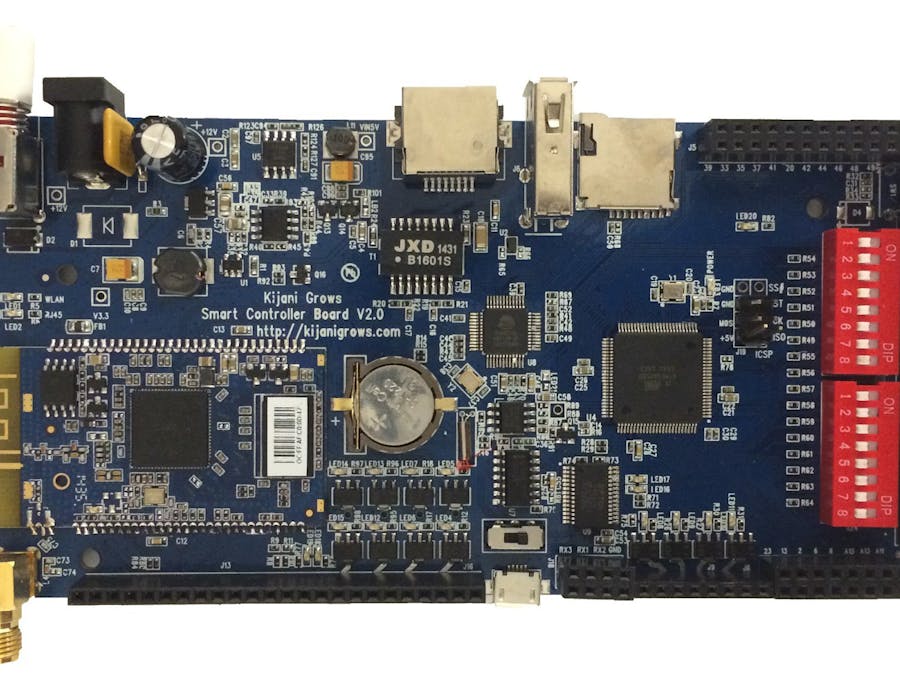
- Using Ethernet, connect the v2 controller to your computer. Use a usb to ethernet adapter if required. Connect a 9vdc power supply to the v2 controller as shown below.
- Connect the v2 controller to your laptop using ethernet as shown below
- Power the v2 controller by depressing the white power button.
- Your computer will be assigned an ip address 192.168.73.x by the v2 controller if it is dhcp enabled.
- Using an internet browser, point your browser to the dhcp assigned network by entering the url http://192.168.73.1 and press the return button. Login with the username ‘root’ and password ‘tempV2pwd’
- On the System menu bar, click on ‘System’ from the dropdown list. On the System menu bar, click on ‘System’ from the dropdown list. You can optionally change the default board name and timezone hereType in the new device name in the ‘Hostname field. You can change the Timezone here as well. Click ‘Save & Apply’. Depress the power switch Off/On for the new hostname take effect.
- While still connected using ethernet and dhcp. Access the v2 client using the url http://192.168.73.1. Select the ‘Network’ from the menu, then select Wifi from the drop down list as shown below.
- On the Wifi menu click on the ‘Scan’ button and select your Wifi Network from the list using the ‘Join Network’ button as shown below.
- Enter the security credentials for your network click the Submit button. The status wireless icon should turn blue and indicate the strength of the connection. Click on ‘Save & Apply‘ to complete the Wifi configuration as shown below.
- Confirm your Wifi connection using the status menu. From the ‘Status’ menu, select the ‘Overview’ option. Ensure you have an IP address In the Network section.
Double check your Wifi Security credentials if controller did not make a connection in the Wireless Security tab shown above.
Registering Your Device Remotely- In a browser navigate to http://api.kijanigrows.com/v2/devices/list. You should see your device name in the device list as shown below. It should appear without any color on the name and the time fields should increment every few seconds.
If not, double check your device Hostname and Wifi connection.
Assembling the sensorsSensor parts- We will now build our sensor box and mount sensors on this. The sensor box and components parts are shown below:
The following parts are found in the sensor kit:
- Sensor box
- Humidity / ambient temperature sensor
- Proximity sensor
- Light level sensor
- Fish tank float level sensor
- Water temperature sensor
- Capacitance growbed sensor
- Wires
- Heat shrink tubing
- Screws and bolts
The sensor box parts are shown below.
- We begin by wiring the sensors that go on the sensor box as shown below with the proximity sensor. Red and Green are always +Vcc and Gnd respectively. The yellow wire is the data line for this sensor. Cut each wire length to about 1.5’. Tin the sensor contacts and stripped wire ends using solder. Solder the wire ends and pins together. Insert the heat shrink tube and shrink this using hot air (eg, a hot air gun, hair dryer etc).
- Wiring the humidity-temperature sensor. Red and Green are always +Vcc and Gnd respectively. The blue wire is the data line for this sensor. After soldering the wires and shrinking the tubes, fold the pins towards the backside gently but firming as shown below. Do not unfold the pins after this(or they may break).
- Wiring the photocell light sensor. This sensor does not have polarity. One end is the data line and the other is goes to Gnd.
- Insert the light sensor and humidity sensor pins through the sensor box as shown below:
- Insert the proximity sensor from the back as shown below. Orient in search a way that the side pieces of the sensor box fit. Ie ..with the wire header on the right of left side when the sensor box is held upright.
- Tack the proximity corners using hot glue. Try not go glue beyond the sensor width so as not to block the side pieces of the sensor box from closing together.
- Tack the photocell and humidity sensors using hot glue as shown below:
- Fold and tack the photocell light ldr sensor pins downwards using hot glue as shown below.
- Fold the ldr wires again upwards and tuck these using hot glue again as shown below:
- Tuck and glue the wires from the humidity sensor as shown below
- Next tuck and secure the proximity sensor using hot glue as shown below.
- Tack the front edges of the passive Infrared sensor PIR sensor with some hot glue as shown below.
- Add the side wall using the screw and nut as shown below.
- Add the other side and secure using the t-slot.
- Next we add and secure the end piece as show below:
- Finally we add the top piece as shown below.
- We will now complete the wiring of the sensor box. All the sensors require grounding, where the proximity sensor and the humidity sensor require +Vcc. To simplify wiring we will connect all the sensors to a common power source. We begin by sniping all the ground(green) and +Vcc to a manageable length say 2” long as shown below (do not snip the data lines from each sensor).
- Strip the power wires and twist the stripped ends together. For the ldr sensor, you can use either wire as ground and the other as data. The ldr is the black wire below.
- Tin the stripped end using a soldering iron and solder, shown below.
- Strip and solder the tips of one of the longer red and green wires that got clipped off from the sensors earlier. Solder and connect the wire with the power wires from the sensor box as shown below (only better, i iron was too hot).
- Cut out short sections of the heat shrink sleeve, just enough to cover the soldered joints (~1cm) and slip these through the other end of the ground and +Vcc wires as shown below.
- Shrink these using hot air such as from hot air gun or a hair drier to make an electrically and mechanically joint as shown below.
- We address the other ends of the wires from the sensor box by terminating them with pcb header pins as shown below. Insert the heat shrink sleeving before soldering the wire to the pin.
- After breaking off and shrinking the pcb head, the pin should look as shown below. Repeat for the rest of the sensor data and power wires.
- The completed sensor box with 3 data and power connections is shown below.
- The float sensor is used for the fish tank level and goes inside the fish tank, the wires are normally long enough, we will terminate this with PCB header pins directly as shown below.
- The one-wire temperature sensor measure the water temperature inside the tank. Shorten this to about 1.5” as shown below.
- Terminate this with PCB pin headers and secure with heat shrink tubing as shown below.
- To determine the level of water in the growbed, a capacitive sensor is used inside the growbed. We will build this from the copper plates, 1M ohm resistor, heat shrink tubing and some wires as shown below.
- Begin by soldering the resistor to the copper plate and add connection points for the wires as shown below. You may need to scrap out the waterproofing layer on the plates at the solder points only to make a good connection.
- Using wires, pcb header pins and heat shrink tubing complete the sensor as shown below. The second plate connects to ground (green) while the other two the blue and black are the data send and receive respectively.
- The prepared sensors are shown below.
The float sensor and the temperature sensor go inside the fishtank. We will now build the sensor fixture. These are mounted underneath the growbed using paper clips and a t-slot adapter as shown below.
Complete sensor fix accessory picture.
The sensor fixture parts are shown below.
- Begin by straighten out the paper clips. Mark one of the paper clips as shown below using a felt pen or sharpie at 1 cm, 2 cm, 6 cm and 10 cm from one end.
- We will make the sensor clips using a long nose pliers to secure the wire on the markings then folding to create a right angle.
- Fold the wire to create right angles at the 1 cm and 2 cm markings as shown below.
- At the 10 cm mark, snip or break the line by holding with a pliers and folding repeatedly.
- Make a circle from the 10 cm end with a circumference to the 6 cm marking as shown below.
- Fold the loop so it is perpendicular to the steam as show below.
- .Run the wires from the floats sensor followed by the float sensor stem into the loop we just created as shown below.
- Lock the sensor using the o-ring(for storage if available) and the nut as shown below.
- Using your sharpie or felt pen, measure and mark out the second wire at 1 cm, 2 cm, 5.5 cm, 8.5 cm and 12.5 cm as shown below.
- Create right angle folds at the 1 cm and 2 cm like we did for the float sensor clip. Then create a loop from the 5.5 cm mark to the 8.5 cm mark as show below.
- Bend the loop so that it is perpendicular to the right angle folds as shown below.
- Create another loop from the tip of the clip to the 8.5 cm mark as shown below.
- Bend the first loop so the bottom end i parallel to the right angled folds as shown below.
- Bend the lower loop until it is parallel to the upper loop as shown below.
- The wire clip is shown with the temperature sensor inserted.
- The clipped sensors and mounting adapter are shown below.
- Straight out some the wire on the float switch end and insert into the mounting adapter as shown below.
- Rebend the right angle corners on the wires as show.
- Insert the wire into the next hole as show below.
- The float sensor should look as shown from the under once fully inserted.
- Next insert the temperature sensor the same way into the next two holes on the adapter as show.
- The tank sensor accessory should appear as shown below.
The tank sensor accessory mounts on the bottom of the story board. These parts are shown below.
- Push the sensor wires through the tanks sensor adapter as show.
- The tank sensor accessory mounts to the t-slot on the bottom of the storyboard panel show below.
- This slots into the bottom base panel in the section shown below.
- Begin by pushing the sensor wires from the float switch and temperature switch through the bottom panel from the bottom.
Add image pushing wire from bottom.
- Bring the storyboard panel close into it’s position and make the sensor wires run along the wire slots in the storyboard as shown below.
- .Push the storyboard in the base slot, and mount the tank sensor adapter as shown below.
- Secure the sensor adapter to the storyboard at the bottom of the base panel using a nut and bolt as shown.
- This should look as shown below when mounted with the wires running on the inside (not garden side).
The overview schematic and pinout for the sensor connections are shown below.
The sensor pin connections shown above on the v2 board are indicated below:
V2 sensor connectionsThe following steps for connecting the sensors are done without the enclosure shown for clarity.
- Start by configuring the dip switches – flick switches 1,2,8 to the ON position as shown.
- Connect the sensor box power lines to the v2 controller on any +5V and GND as shown below.
- Connect the humidity sensor wire to pin 27 as shown below.
- Next we connect the proximity sensor to pin 6. Well the diagram below shows the connection on pin 23, shift this to pin 6. The point is it does not matter so long as it is a free pin, we configure them all the same way as will be seen in a bit.
- The sensor box wiring for power and 3 data lines is shown below.
- The completed v2 controller and wired sensor box is shown below.
- Next we wire the tank sensors to the v2 controller starting with the fish tank temperature sensor on pin D26, +5V and GND as shown below.
- Next connect one of the wires from the float switch to D8 and the other to any ground, such as the GND next to D23 as shown below.
- The garden, sensor box, tank sensors and v2 enclosure with the front panel removed are shown below.
- The sensor mounts onto the front panel using the slots shown.
- The sensor box is shown by the attachment, the hooks slide into the holes while the wires from the box will run through the middle slot as shown.
- This is inserted from the top and slides straight down as shown.
- Push gently yet firming until it is completely inserted as shown below.
- Now we can run the wires through the enclosure. We start by tearing off the slot next to the reset switch as shown.
- Rip this part off as shown.
- The wire opening is shown below.
- The tear open the sides of the flap on the top side as show below.
- Then close the enclose with the flap on the inside or outside as shown.
- Then insert the wired enclosure into the control cavity in the garden as shown.
- The controller is shown inserted into the control slot below.
- This is shown with the controller inside the control chamber.


Comments