

Hardware components | ||||||
 |
| × | 1 | |||
| × | 1 | ||||
 |
| × | 1 | |||
| × | 1 | ||||
 |
| × | 1 | |||
 |
| × | 2 | |||
 |
| × | 1 | |||
| × | 1 | ||||
This project is for my class at Rice University: EDES 301, Introduction to Practical Electrical Engineering.
StoryI decided to make this project because I have been wanting a coffee mug warmer for a while, as I drink a lot of coffee and tea, but it takes me a while to drink sometimes, and it gets lukewarm or even cold before I finish it. I want to be able to enjoy my drink at the pace that I want without having to sacrifice the flavor or my enjoyment.
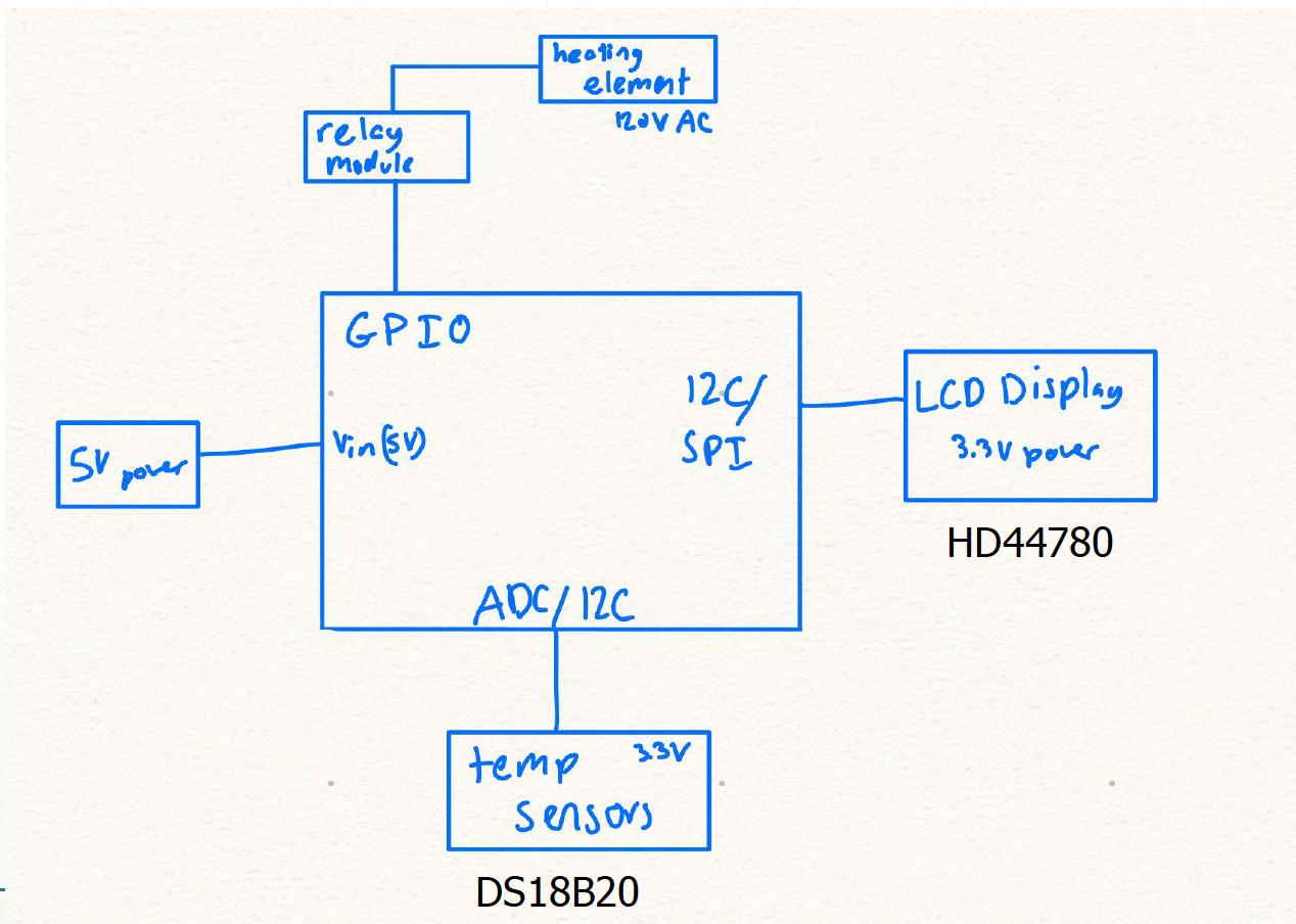
HardwareFor my project I used a pocket beagle as the microcontroller. This is the pinout of it:
Unfortunately I was not really able to add any pictures as the wires were messy once put into the box so it is difficult to show how everything is connected.
The temperature sensor was the hardest to step up. It is a one wire configuration meaning that you have to set up the board for it. You have to use a linux drive which I have included in my github. The wires are like this: GND: ground, DAT: P2_33 and VCC goes to 3.3V. I added a pull up resistor between the data and the VCC.
For this part you you have to use the configure pins that I put into my github. You have to power the relay with the 5V (the 5 volts comes from the V_in P1_7) and ground. You then have to put one side of the heating pads into the middle of the relays that you have chosen to pick (I used 2 and 4). With the ones you pick you also have to connect it to the pocketbeagle pins that you configured as GPIO (I used P2_32 and P2_34). The other wire on the heating pad should be connect to ground. In my configuration I wanted the heating pads to be off until I turned them on using the relay so I put 5V into the right.
This button is what is used to turn the coffee heater on and off. I connected one pin to P1_33 with a resistor between 3.3 V and that pin and the other to ground. Make sure you use the same side of the button.
4. PotentiometerThe potentiometer is used to control the desired temperature. It has three legs. The middle leg is connected to P1_19. One leg is then connected to ground while the other is to the 3.3V rail.
5. LCD ScreenThe LCD was the most difficult to wire. These are all the pinouts for the information: RS: P1_2, E = P1_4, D4: P2_18, D5: P2_20, D6: P2_22, D7 = P2_24. Once those are set up you also need to have a potentiometer wired in. The middle pin will connect to V0 while one pin is grounded and the other one gets 3.3V. The potentiometer allows the letters to show up. Once it is powered twist it until the blue boxes pop up on your display. You also need to ground BLK, RW, and GND. VDD and BLA will both get 3.3V.
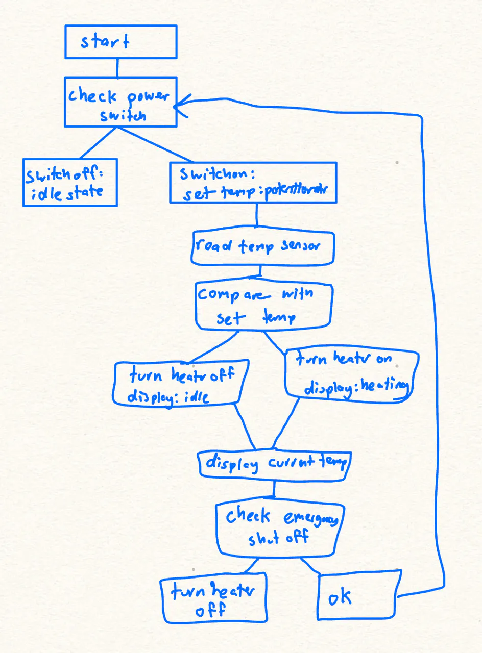
Starting the coffee heaterTo start the coffee heater you have to connect it to your computer and run the command. You can then set the temperature using the potetntiometer with the desired temperature on the display. You also have to put the temperature sensor into your mug and place the mug on the heating pads. Once all that is set up you can press the button, sometimes you have to hold it down for a little. You will then hear a click from the relay module and you can also see on the display screen that it will say heating. The heating pads will stay on until the temperature sensor is at reading the same as what you set the temperature to be and the relay modules will switch to off and the screen says done. You can press the button again to turn it off.
Future worksChecklist for publicationI think that the most pressing issue is just that I miscalculated my dimensions of my box itself but also the error that came with the laser cutter as the box was meant to fit into each other with grooves but that did not happen so I had to super glue things which made the design not look good.
Also, the connections of the wires to the components once mounted onto the box were not the most secure so it would be a good idea to solder or connect them in some way.
Other than those the wiring was a bit messy but it all functioned well and my code ran well.


_3u05Tpwasz.png?auto=compress%2Cformat&w=40&h=40&fit=fillmax&bg=fff&dpr=2)
Comments