


Software apps and online services | ||||||
 |
| |||||
*******
Please visit https://proteshea.com/sending-commands-from-host-to-arduino-uno/ for a complete list of materials needed for this project.
*******
IntroductionIf you haven’t read our Getting Started Guide or Project 3 for the Arduino Uno Rev3(Uno), please read those first. Otherwise, continue reading. In the last tutorial, we sent data from the Uno to the host and in this tutorial, we’ll be sending data from the host to the Uno. We interface a 10-segment LED bar graph and communicate with the host via UART. Based on the received data from the host, the Uno will display a certain binary number on the bar graph. We’ll use 4/10 LEDs on the bar graph and each LED input will be an output from the Uno.
LED Bar GraphPlease see Arduino Uno Rev3 Project 1 to learn more about the LED bar graph and internal circuitry.
Serial TerminalPlease see Arduino Uno Rev3 Project 3 to learn more about the serial terminal.
Resistor ArrayPlease see Arduino Uno Rev3 Project 1 to learn more about the 470 ohm resistor array.
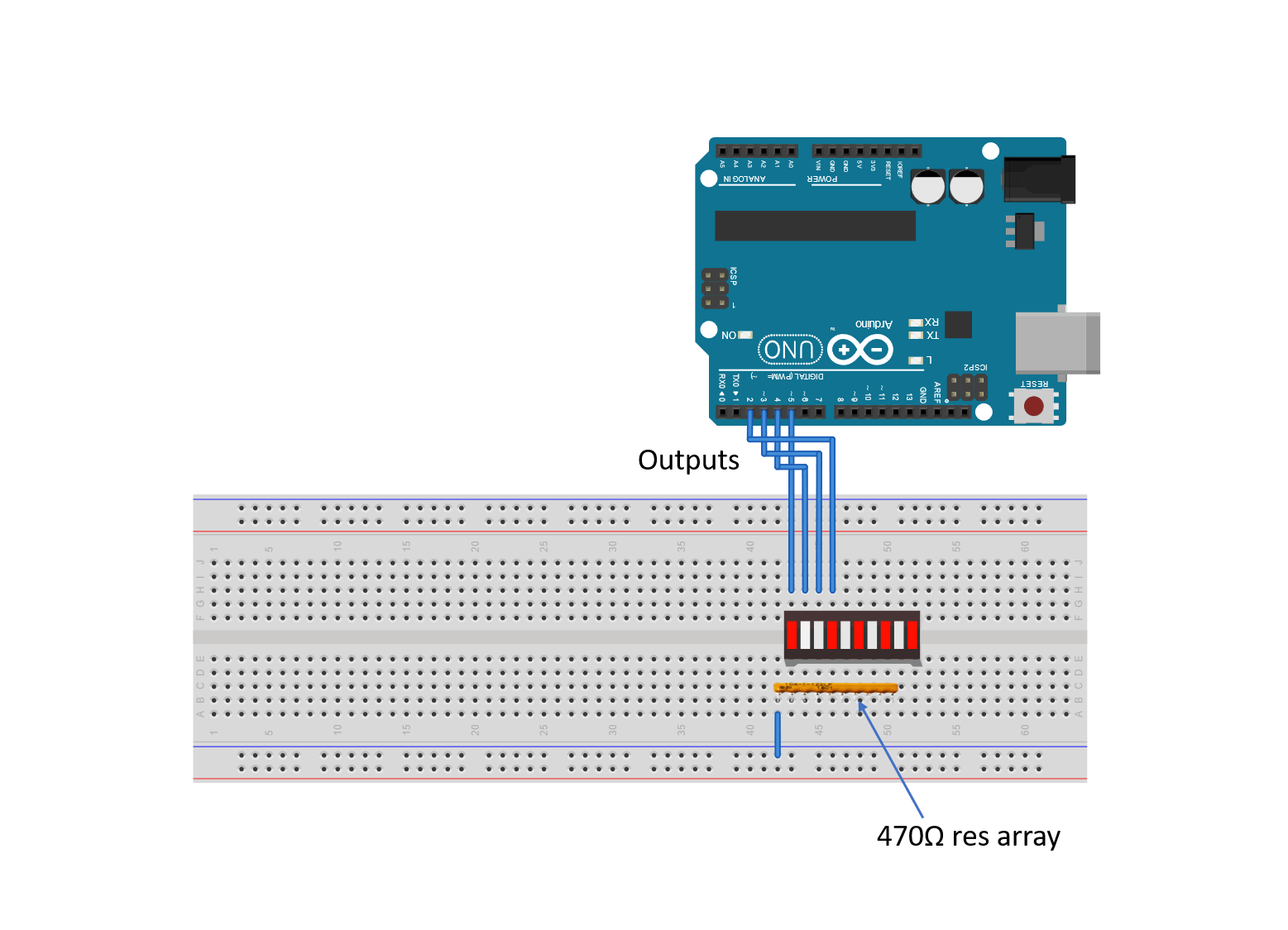
WiringI’m using a breadboard instead of Modulus since almost everybody has a breadboard. First, let’s place the LED bar graph onto the breadboard. Insert both so that the body is over the valley of the breadboard. You do not want the pins to short each other by being connected to the same node. Next, place the 470 ohm resistor array on the cathode side of the LED and tie pin 1 of the array to GND. Make sure that pin 1 of the resistor array is not connected to any of the cathodes of the LED bar graph.
Next, use a M/M jumper to wire the anode side of the LED bar graph as outputs to Uno pins 2-5. For example, pin 10 of the bar graph will get wired to Uno pin 5, pin 9 of the LED will get wired to Uno pin 4, and so on. This is shown in the image below.
If you haven’t mounted the Uno onto the prototyping area of the FuelCan, go ahead and do that. I placed the breadboard in the bottom storage compartment to limit the length of the jumper wires. We need to supply GND to the and ground rail on the breadboard by using the provided banana jack to test-lead clip cable to do so. You will need one male header pin to mount the test-lead clip to on the breadboard side. Plug the Type A side of the USB cable into the USB1 receptacle and the Type B side into the Uno’s receptacle. Then, plug in the Type A to Type A USB cable into a USB port on your computer and the external USB connector of the FuelCan. Power up the FuelCan with the AC-DC power adapter.
SoftwareOnce the wiring is complete and the FuelCan is powered up, we can now load the sketch onto the Uno. The sketch is below. Open up the Serial Monitor within the IDE. Notice in the code that there is a switch statement to choose the correct LED output based on the input received from the host. For example, if we send a 1 to the Uno, the code inside of case 1 will execute.
There are cases 0-9 so send each number to the Uno and look at the output of the LED bar graph. It should be displaying the binary equivalent of the number received. There is also a line in the code, Serial.print(RXdata), which sends what the Uno receives back to the host. This is a good debugging technique to use since you can verify what data is being transmitted and received. When you send a ‘1’ to the Uno, notice the data received back on the Serial Monitor – it shows 4910. Why? The data is converted to ASCII. The ASCII equivalent of 1 is 49 and the ASCII equivalent of ‘New Line’ is 10.


Comments