


Hardware components | ||||||
 |
| × | 1 | |||
 |
| × | 1 | |||
| × | 1 | ||||
| × | 1 | ||||
 |
| × | 1 | |||
| × | 1 | ||||
| × | 1 | ||||
 |
| × | 1 | |||
| × | 1 | ||||
| × | 1 | ||||
| × | 1 | ||||
| × | 1 | ||||
| × | 1 | ||||
| × | 1 | ||||
| × | 1 | ||||
| × | 1 | ||||
| × | 1 | ||||
| × | 2 | ||||
| × | 1 | ||||
| × | 1 | ||||
| × | 1 | ||||
| × | 1 | ||||
| × | 1 | ||||
| × | 1 | ||||
| × | 1 | ||||
| × | 1 | ||||
| × | 1 | ||||
| × | 1 | ||||
 |
| × | 1 | |||
| × | 1 | ||||
| × | 1 | ||||
| × | 1 | ||||
| × | 1 | ||||
| × | 1 | ||||
Software apps and online services | ||||||
| ||||||
 |
| |||||
_4YUDWziWQ8.png?auto=compress%2Cformat&w=48&h=48&fit=fill&bg=ffffff) |
| |||||
 |
| |||||
Hand tools and fabrication machines | ||||||
 |
| |||||
 |
| |||||
| ||||||
 |
| |||||
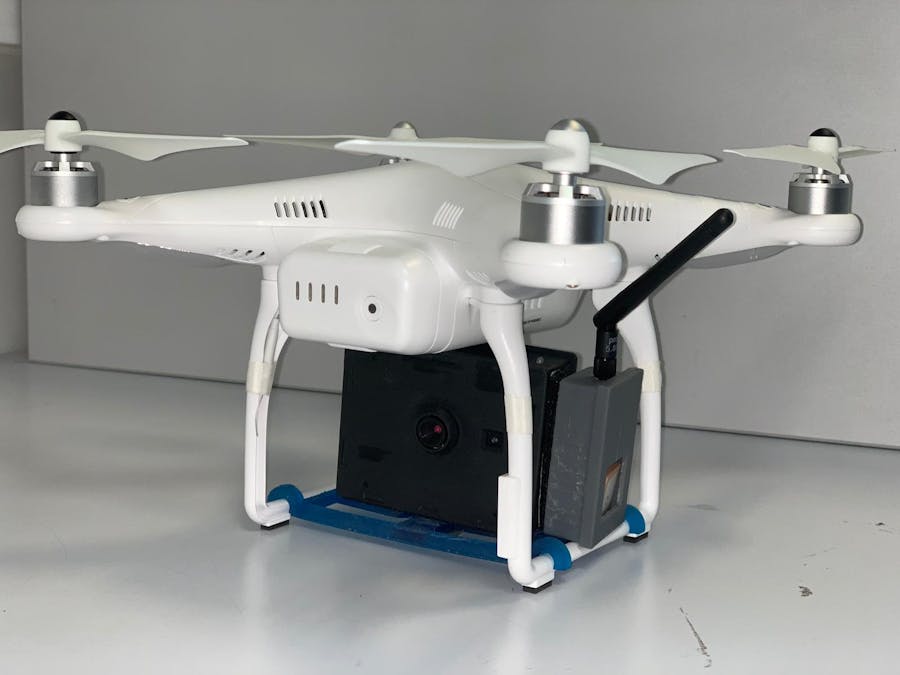
As part of our school project, at Polytech Sorbonne (Paris, France), we designed a tiny module able to transmit wirelessly thermal images from a Lepton FLIR 3.5-based camera. This camera was designed to detect Asian hornet nests.
Asian hornets have a direct impact on honey bee colonies by killing honey bees to feed themselves. This hornet endangers apiculture. However, their nests, despite being usually well hidden, has to be thermoregulated to 30 degrees, constantly.
This allows a farmer to detect a nest without endangering himself, by flying a drone equiped with our thermal camera and look for places where he couldn't reach by himself, when for example he flies nearby a tree and find something that is nest-shaped like and warm enough.
This thermal camera is based on Max Ritter's DIY Thermocam, that you can see with this link: https://github.com/maxritter/DIY-Thermocam/tree/master/Documents
You need first to build the thermocam. You'll find attached a PDF file to build your own thermal camera, once you have purchased all the components required (we advise you to fully read this article first, to understand every part in this project and how it works).
Once you've finished to assembly you thermal camera, you'll next have to build the wireless module.
The wireless modules consists of a Raspberry Pi Zero, a GPS module, and a 5.8 GHz transmitter, and a voltage regulator for the transmitter.
Make your own :
You'll find every piece of information to build your own in the attachment section.
We recommand you to follow this order:
- Print every 3D part of the project, using the "All 3D files" folder.
- Order your PCB, using the "Gerber and KiCad files" folder.
Once you've received every of the parts above, you can follow the assembly guides for the wireless module and the thermal camera. Next, you should :
- Read the how to program the wireless module guide.
- Read the how to use the EI2I Thermocam guide.
You should be ready to have a flight with thermal vision!
What's Inside Our Project?Core Processing Unit:The Teensy 3.6 features a powerful Cortex M4F processor from NXP(MK66FX1M0VMD18), with a core frequency of 180MHz, that can be overclocked up to 240 MHz. Other features are 1MB of flash space and 256KB of RAM. This internal memory allows full-screen rendering with a resolution of 320x240 px.
The visual camera uses an OV2640 image sensor from OmniVision, with a maximum resolution of 2MP and has a very compact form factor with no big lens attached. It sends data to the CPU over SPI protocol, enabling fast speed transmission. The image sensor can be configured over the I2C protocol. This allows for example to set the image type (RAW or JPEG) and the resolution, as we can choose from 160x120 to 640x480 px.
This third generation of the FLIR Lepton sensor has a thermal raw resolution of 160x120 pixels.
Similar to the visual camera module, the configuration of the Lepton is done over I2C, whereas the data is transferred over the SPI interface, with a clock speed of up to 20 MHz.
The shutter attached to the lens opens and closes automatically, when required. It provides a uniform surface, that can be used to recalibrate the active pixel array and removes noise from the image. This shutter can be triggered when needed, manually or automatically.
This is the element where we had the biggest footprint. Max Ritter's Thermocam have an UART interface so it can communicate and live stream to a computer, thanks to different orders sent via serial sent commands.
It had to be ported to the raspberry Pi Zero. We wanted to have the smallest module as possible. During the development of the project, we weren't sure concerning the method of sending the thermal live video to the ground. Whether using WiFi, or 5.8 GHz Analog transmission. Since we had little time, and we wanted to prevent any changes, we wanted to go with the RPI0w.
But why would we use a raspberry Pi as we already have a Teensy ?
Because the Teensy does not offer any video output capabilities like a Raspberry Pi does, plus, the Raspberry Pi Zero offers an analog output possibility.
The thermal image is not rendered on the Pi Zero itself. Instead, the display buffer from the Thermocam is transferred as whole, using a serial connection at 115200 bauds, what increases the refresh rate.
A python script running on top of the Linux operating system receives the data from the camera and creates a thermal image stream with a resolution of 640x480 pixels, from the buffer who is at 320x240 pixels, made possible by the pygame "pygame.transform.smoothscale()" function, that uses a method based on bilinear and averaging code.
Since we had no big resolution to send, analog transmission seemed for us to be the less constraining solution. WiFi doesn't like obstacles, and when we fly a drone, we can meet a lot of these. That's why we opted for a 5.8 GHz analog transmitter as used by FPV drone flyers in order to keep a really strong connection even at 1.5 km from receiver.
A GPS sensor needed to be added to this project. We wanted to have the user of the wireless module to know where he is at any given moment, especially when flying a drone.
Thus, we needed to find a GPS module suited to the criter of having a small form factor. We found this module in our school, you can find yours at the link we attached in the "things" section.
This GPS uses UART protocol to communicate. First, we had trouble dealing with this, this the UART controller on the Raspberry Pi Zero was already used to receive the video buffer from the thermal camera.
Thus, we needed to find a solution to communicate with our GPS without interfering with the UART controller. And we had this idea of "bit banging" :
We can use two GPIO pins on the Raspberry Pi to “Bit Bang” data in, which is a “Software Serial” port rather than needing a 2nd Hardware one. We used the PIGPIO library in order to bit bang and having access to the GPS. You'll find attached the Python file, and all the procedure you have to follow before enabling the wireless module.
We managed to communicate, by using this method, to communicate with the PGS module at a baud rate of 4800, which is more than enough to receive the NMEA protocol datas.
You can find an explanation on how the NMEA protocol works here :
http://www.cedricaoun.net/eie/trames%20NMEA183.pdf
Finally, when the user landed the drone, he can find in the SD card equiped in the Raspberry Pi Zero a history of the GPS coordinates of where he went with the drone. This file is named "history_gps.txt" in the boot partition of the RPI.
Afterwards, we attached a script in order to have a graphical path to represent where is went on a map based on the coordinates file present on the SD card.
We've made a python script to see where you've been with your Drone.
You'll see in the attached section a guide on how to use it and display on a map every location of where you went.
The PCB layout has been made to connect everything up. It is a 89.4 mm by 68.4 mm 2 layers PCB, with 1.6 mm of thickness.
Here, at Polytech Sorbonne, we have the chance of having a CNC machine that can build up our PCB, but if you don't have this kind of hardware, thanks to the Gerber files we attached, you can easily order your pcb from manufacturers, as PCBway.com, they'll only charge you 1$/PCB.
Same as for the PCB, our school is equiped with 3D printers.
You'll find attached the 3D files (.Stl), ready to be printed.
Finally, having a thermal camera flying, can be used for many others purposes, like rescuing, firefighters or police services.
We can imagine this thermal camera used to recognize the field, identifying fires, or spotting people.
It can also be used for building analysis, where you can see whether a thermal isolation of a house is good or not.
ConclusionWe can have a look here at the comparison table:
Additional cost for the wireless module: 53€
As part of the 50 hours project of the second semester of our 4th year at Polytech Sorbonne, we designed a wireless transmitter for the thermal camera proposed by Max Ritter.
We finally managed to keep the additionnal module at a low price : usually, on the market, you have a similar product for nearly a thousand dollars, for the least pricey ones. Here, the wireless module costs 50€ and keeps an honourable image quality and refresh rate.
It is totally open-source, you'll find attached here every document and code.


_Ujn5WoVOOu.png?auto=compress%2Cformat&w=40&h=40&fit=fillmax&bg=fff&dpr=2)


Comments