

_wzec989qrF.jpg?auto=compress%2Cformat&w=48&h=48&fit=fill&bg=ffffff)
_ztBMuBhMHo.jpg?auto=compress%2Cformat&w=48&h=48&fit=fill&bg=ffffff)
After discovering the Arduino platform, I was amazed and my dream of one day developing my own electronics became true.
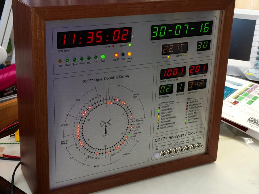
As anyone will do, I started with the basic sketches but soon I wanted to make something useful. As I always loved Radio Clocks (they synchronize with the DCF77 signal from Germany in my case), I decided to make a clock which did not only show the time but a clock which shows me what is going on.
After hundreds of hours tinkering, making uncountable mistakes, I finally had a working clock with my own code and printed circuit board designs.
Photos and videos of DCF77 Analyzer/Clock v1.0:
But later I discovered the DCF77 superfilter from Udo Klein which provides a clean signal when the radio signal is not so good.
This is a separate Arduino Uno board with the Superfilter software, (you can look at it as a stand alone 'black box', filtering the signal) connected between the DCF77 antenna and the Arduino Mega running my sketch.
So I made a 2.0 version of the first clock:
- completely rewritten code
- extensively commented so hopefully anyone can understand what's going on
- added a PIR movement sensor to reduce power consumption
- added the DCF77 Superfilter
- extra display for temperature or other use (like Sun rise/set time)
Photos and videos of the new DCF77 Analyzer/Clock v2.0:
Demoto view the video click HERE
Build in 'Grandfather Clock'to view the video click HERE
The DesignThe front panel and casing:
The design of the front panel was made in a freeware program called Inkscape (see the download URL at the beginning of this page).
Actually producing the front panel proved to be the hardest part. I spent a lot of money trying to make it at a local FabLab using a laser cutter and a special kind of Acrylic with an aluminium like coating. The idea was to cut the holes with the laser and engrave the text and lines by burning away the very thin coating exposing the black acrylic below. But this was a nightmare as the laser cutter was not able to produce within the tolerances I needed due to heavy use and 'abuse' by many users.
Then I came across an online Photo service. They print on all sorts of materials and one of those was a DiBond panel. The price was very good, 28 Euro's including postage. But the result was at first disappointing because they did not print my design 1:1 but slightly enlarged. So beware if you decide to use this method. Call them first and ask if it is possible to print 1:1.
After a phone call they sent me another panel with the right dimensions. It was better than expected, excellent!
Then a lot of drilling and routing was needed:
/*
 ================================================================================
 DCF77 Analyzer / Clock version 2
 ================================================================================
 This sketch is free software; you can redistribute it and/or
 modify it under the terms of the GNU Lesser General Public
 License as published by the Free Software Foundation; either
 version 2.1 of the License, or (at your option) any later version.

 This sketch is distributed in the hope that it will be useful,
 but WITHOUT ANY WARRANTY; without even the implied warranty of
 MERCHANTABILITY or FITNESS FOR A PARTICULAR PURPOSE.  See the GNU
 Lesser General Public License for more details.

 You should have received a copy of the GNU Lesser General Public
 License along with this library; if not, write to the Free Software
 Foundation, Inc., 51 Franklin St, Fifth Floor, Boston, MA  02110-1301  USA
 ================================================================================

 This C++ code is far from optimized because I myself am an Arduino and C++ novice.
 But even after learning some more now, I want to keep the code simpel and readable.
 That is why I maybe over-documented the code to help understand what's going on.

 Erik de Ruiter
 2014-2020


 May 2014 First version
 March 2016 - big overhaul...
 July 2016 - Start with building the 2.0 Clock and adapting the sketch

 Version 2.1 date 2020-01-18
 - Powersafe function fixed.

 Version 2.0
 - This sketch is adapted for my 2.0 version of the DCF/Analyzer Clock. It used the Arduino MEGA and the DCF Superfilter
   by default and to drive the many seperate LED's I now use the ports of an Arduino Mega instead of a Maxim 7219 chip.
   This is because driving LED's with many different Voltage/Current specs is problematic with the Maxim chip.
   Lighting additional LED's for expample will influence (dim) the LED's already on. As I'm not an electronics engineer
   my only solution was to use the extra ports of the Arduino Mega. Ofcourse you can use transistors or extra chips to
   drive the LED's but for me this was the obvious solution.
 - Removed all the Maxim Common Anode display code


 Version 1.72
 - Option: Use a cheap Ebay PIR detector to shut off selectable display's when no activity is detected.
   The switch off delay can be set by the user to prevent the display shutting of if a person
   is not moving but the display should be on.
 - Now the display Night shut-down can be disabled by making both values 'POWERSAVINGOFFTIME'
   and 'POWERSAVINGONTIME' zero.
 - Fixed temperature display not shutting off at powersave mode.
 - errorCounter display did not reset every hour -fixed

 Version 1.71
 - User option to reset temperature min/max memory at midnight

 Version 1.7:
 - The resolution of the temperature display is improved: from 0.5 to 0.1 degrees Celsius
   Because of the time the DS18B20 sensor needs to convert the temperature and to keep the code clean,
   the temperature display is updates once per minute.
 - Parity check routine optimized.
 - More reliable check for bad DCF data, preventing RTC update with invalid data.
 - EoB error now clears inner LED ring as it should.
 - The DCF OK LED now displays the condition of the DCF signal more reliably. Turns off immediately if an error occurs
   and only turns ON when all 3 parity bits are OK.

 Version 1.6:
 - Changed temperature function to only calculate once per minute. Got strange errors before the change because
   I used a delay of 100ms to give the DS18B20 sensor time to calculate the temperature. But the delay function is
   a very bad idea in most c++ code so I finally got rid of it.

 Version 1.5:
 - Complete overhaul of the scanSignal function and the rest of the code! My first attempt worked but could be improved...
 - The rPW and rPT led's did not work as I intended so that is corrected now.
 - The End of Buffer error check routine does work now as it should.
 - I incorporated a Parity check of the incoming DCF signal. In the signal 3 Parity bits are sent so now these are
   checked and only if all three are OK, the received time information is accepted, the display is updated and the RTC synced.
   if desired, you can attach 3 extra dual-color LED's (Common Cathode) to see if each of the 3 Parity bits are OK or Failed.
 - I made wiring (or changing the wiring) much easier I think by putting all the PIN config in one easy to read table
 - As long as you use 1 DS18B20 temp. sensor, I edited the code so you no longer need to figure out the address of the I2C device.
 - Big clean-up of the code...
 - Powersaving by shutting off the displays (the clock remains functioning as normal)
   can now be configured somewhat easier by editing two variables POWERSAVINGONTIME and POWERSAVINGOFFTIME.
 - changed some variable names:
   - Maxim instances 'lc' and 'lc1' are now MaximCC and MaximCA
   - Display description MaximDcfTime is now DisplayTempWeek
   - DCF77SOUNDPIN is now BUZZERSWITCHPIN
 - LED/Display test after power up now build in


  Short description:

  Power On:
    After power-on, first a LED test is performed. The LED's and displays lite up sequentially to keep the power consumption low.
    Then the clock starts receiving DCF pulses and when a Minute Mark (2 seconds gap) is detected, the Minute Marker LED is lit
    and the buffer counter is reset. The inner LED ring now will show the incoming DCF pulses which are also stored in the buffer.
    At 3 moments during reception of data the parity DCF bits are checked to see if the data is valid.

  Valid data received:
    When, at the end of the minute, after the Minute Mark is detected (BF (Buffer Full) LED is lit), all three parity bits are OK
    ('DCF OK' LED is lit), the buffer information is used to extract time and date information.
    Then the RTC clock is updated ('RTC Synced' LED is lit) and the inner LED ring information is copied to the outer LED ring.
    The time, date and week display, day LED, summer/wintertime and leap year LED information is updated with the new time information.

  No valid data:
    When one or more of the parity bits are not OK because of a noisy signal, receiving of DCF information is continued but
    will not be used to update the RTC, display's and LED's. The outer LED ring, 'RTC synced' and 'DCF OK' LED's will be reset.
    Time, date, week, day LED, summer/wintertime LED and leap year LED are not affected and keep displaying the last received valid values.
    The 'Period Time' and/or 'Period With' error LED's will indicate the error(s) and the error counter display is updated.
    Every hour, the error display will bet set to zero.
    The EoB, End of Buffer LED is lit when more DCF pulses are received before the Minute Mark is detected due to a noisy signal.
    (When a minute Mark is detected we should have no more than 58 bits/pulses)
    After the detection of the Minute Marker, a new cycle is started.

  Temperature:
    At the 30 second mark, the temperature display will show the High and Low values of the past period after the last reset.

  Chime:
    If the CHIME switch is ON/HIGH, then at the beginning of each hour, the Chime (if connected) will sound
    At night time, a time set by the user in the code itself, the chime is disabled.

  Power saving - display's shut off
    This will only work IF the Power Save switch is HIGH:
    1. NIGHT SHUT OFF
       At times set by the user, the displays are shutt off at night and turned on in the morning.
       Look at the POWERSAVINGOFFTIME and POWERSAVINGONTIME variables.
       Check the function <turnDisplaysOff> to select WHICH displays you want to shut off at night.
    2. PIR SENSOR
       Connect a PIR sensor and activate the PIR option POWERSAVE_BY_PIR and the the delay at PIR_DELAY_TIME.
       Every time the PIR detector senses movement, a minute counter is reset but if no movement is detected
       longer than the PIR_DELAY_TIME, the displays are shut off.
       When movement occurs, the displays immediately switch on.
    Note: as said before, the clock will function normally while the displays are shut off.

  DCF beep:
    With a switch, connected to pin BUZZERSWITCHPIN, you can hear the received DCF bits coming in.
    The tone duration is equivalent to pulse width of the DCF bits, so either 100 or 200 ms.

  Miscelleanous:
    When the RTC battery is empty or a connection fault is detected, the RTC Error LED is lit.


 CREDITS:
 I learned a lot from the work of Matthias Dalheimer and Thijs Elenbaas who made their own DCF77 decoders.
 Without their work I would not have known where to start.
 I ended up writing my own code (using bits and pieces of their ideas) so I could understand what is happening...
 My code is far from efficient or advanced but it does work and I know what is going on.

  Interesting websites:

 - Brett Oliver         : http://home.btconnect.com/brettoliver1/
 - Joop Tap             : http://www.jooptap.nl
 - Thijs Ellenbaas      : http://thijs.elenbaas.net/2012/04/arduino-dcf77-radio-clock-receiver-hardware-2/
 - Mathias Dalheimer    : https://github.com/roddi/DCF77-Arduino/blob/master/DCF77Servoclock/DCF77.h
 - DCF77 wikipedia      : https://en.wikipedia.org/wiki/DCF77
 - Much more DCF77 info : http://www.picbasic.nl/indexes_uk.htm

 - My Flickr website    : https://www.flickr.com/photos/edr1924/albums
 - My Github website    : https://github.com/deruiter

 */

//----------------------------------------------------------------------------------------------------------
// Libraries
//----------------------------------------------------------------------------------------------------------

// Arduino (new) Time library .................................... http://www.pjrc.com/teensy/td_libs_Time.html
#include <Time.h>

// Enable this line if using Arduino Uno, Mega, etc.
#include <Wire.h>

// a basic DS1307 library that returns time as a time_t .......... http://www.pjrc.com/teensy/td_libs_DS1307RTC.html
#include <DS1307RTC.h>

// Maxim 7219 displays library ................................... http://playground.arduino.cc/Main/LEDMatrix
// !!! NOTE: you must use a special version of the Ledcontrol.h library to get Common Anode support
// because the Maxim chip is normally only suitable for common CATHODE displays!
#include <LedControl.h>

//SPI interface library .......................................... http://arduino.cc/en/Reference/SPI
#include <SPI.h>

// OneWire lets you access 1-wire devices made by Maxim/Dallas,
// such as DS18S20, DS18B20, DS1822 .............................. http://www.pjrc.com/teensy/td_libs_OneWire.html
// The DallasTemperature library can do all this work for you! ... http://milesburton.com/Dallas_Temperature_Control_Library
#include <OneWire.h>

//----------------------------------------------------------------------------------------------------------
// Arduino UNO Pin connections in an easy to read table
//
// input  - Rx - used for programming/communication with PC
// output - Tx - used for programming/communication with PC
#define DCF77PIN 2           // input  - DCF signal from antenna pcb. Pin must an interrupt input!
#define PIRDETECTORPIN 3     // input  - PIR detector: check for activity in the room to activate displays
#define BUZZERSWITCHPIN 4    // input  - SWITCH - turn on/off DCF77 'beep' piezo buzzer / ON = HIGH, OFF = LOW
#define CHIMESWITCHPIN 5     // input  - SWITCH - turn on/off the hourly chime sound / ON = HIGH, OFF = LOW
#define POWERSAVESWITCHPIN 6 // input  - SWITCH - turn on/off the power save feature so display is always on / ON = HIGH, OFF = LOW
#define TEMPSENSORPIN 8      // input  - Dallas One Wire DS18B20 temperature sensor
#define TEMPRESETPIN 9       // input  - PUSH BUTTON - reset temperature min/max memory / HIGH = reset
#define MAXIMCCLD 10         // output - CS/LOAD - pseudo SPI connection to the Maxim 7219 chip - 7 segment displays
#define MAXIMCCCLK 11        // output - CLOCK   - pseudo SPI connection to the Maxim 7219 chip - 7 segment displays
#define MAXIMCCDATA 12       // output - DATA    - pseudo SPI connection to the Maxim 7219 chip - 7 segment displays
// !! Pins 22 through 53 are only to be used for LED's
#define LED_SUNDAY 22         // output - LED - Sunday
#define LED_MONDAY 23         // output - LED - Monday
#define LED_TUESDAY 24        // output - LED - Tuesday
#define LED_WEDNESDAY 25      // output - LED - Wednesday
#define LED_THURSDAY 26       // output - LED - Thursday
#define LED_FRIDAY 27         // output - LED - Friday
#define LED_SATURDAY 28       // output - LED - Saturday
#define LED_CEST 29           // output - LED - Summertime CEST
#define LED_CET 30            // output - LED - Wintertime CET
#define LED_LEAPYEAR 31       // output - LED - Leap year
#define LED_RTCERROR 32       // output - LED - problem reading RTC data (empty battery/connection)
#define LED_RTCSYNC 33        // output - LED - On when RTC is succesfully synced with the DCF time
#define LED_TEMP 34           // output - LED - temperature is displayed
#define LED_OPTION1 35        // output - LED - optional 1 data is displayed
#define LED_OPTION2 36        // output - LED - optional 2 data is displayed
#define LED_ERRORPT 37        // output - LED - DCF Period Time error
#define LED_ERRORPW 38        // output - LED - DCF Period Width error
#define LED_BUFFERFULL 39     // output - LED - Buffer full indicator, next the data will be analized
#define LED_MINUTEMARKER 40   // output - LED - End of DCF data stream detected before buffer is filled, data is corrupt
#define LED_BUFFEROVERFLOW 41 // output - LED - More data received in one minute than expected due to bad signal
#define LED_DCFSTATUS 42      // output - LED - On when we have good DCF data
#define LED_POWERSAVE 43      // output - LED - Power save mode is activated, some displays are off
#define LED_PARITY1PASS 44    // output - LED - Parity 1 bit is OK
#define LED_PARITY1FAIL 45    // output - LED - Parity 1 bit FAILED
#define LED_PARITY2PASS 46    // output - LED - Parity 2 bit is OK
#define LED_PARITY2FAIL 47    // output - LED - Parity 2 bit FAILED
#define LED_PARITY3PASS 48    // output - LED - Parity 3 bit is OK
#define LED_PARITY3FAIL 49    // output - LED - Parity 3 bit FAILED
#define LED_PIRMOTION 50      // output - LED - On when PIR is detecting motion

// Analog pins
#define BUZZER A7        // output - Piezo buzzer for DCF77 'beep' (to '+' of the buzzer)
#define SPEAKERVOLPIN A6 // output - Sound Board volume - LOW = volume one notch lower. SPEAKERVOLUME determines how many times this output is activated after power on
#define CHIMEPIN A5      // output - Chime Activate - OUTPUT LOW = Activate Chime on Adafruit Soundboard FX
// USED for DS1307 RTC   // I2C DATA  - connect to Real Time Clock pcb
// USED for DS1307 RTC   // I2C CLOCK - connect to Real Time Clock pcb

//----------------------------------------------------------------------------------------------------------
// DS18B20 initialization
//----------------------------------------------------------------------------------------------------------
OneWire ds(TEMPSENSORPIN); // define Onewire instance DS

//----------------------------------------------------------------------------------------------------------
// Maxim 7219 Matrix Display initialization
//----------------------------------------------------------------------------------------------------------
/*
 clearDisplay(int addr) ............................................. clears the selected display
 MaximCC.shutdown(int addr, boolean) ................................ wake up the MAX72XX from power-saving mode (true = sleep, false = awake)
 MaximCC.setIntensity(int addr, value) .............................. set a medium brightness for the Leds (0=min - 15=max)
 MaximCC.setLed(int addr, int row, int col, boolean state) .......... switch on the led in row, column. remember that indices start at 0!
 MaximCC.setRow(int addr, int row, byte value) ...................... this function takes 3 arguments. example: MaximCC.setRow(0,2,B10110000);
 MaximCC.setColumn(int addr, int col, byte value) ................... this function takes 3 arguments. example: MaximCC.setColumn(0,5,B00001111);
 MaximCC.setDigit(int addr, int digit, byte value, boolean dp) ...... this function takes an argument of type byte and prints the corresponding digit on the specified column.
                                                                      The range of valid values runs from 0..15. All values between 0..9 are printed as digits,
                                                                      values between 10..15 are printed as their hexadecimal equivalent
 MaximCC.setChar(int addr, int digit, char value, boolean dp) ....... will display: 0 1 2 3 4 5 6 7 8 9 A B C D E F H L P; - . , _ <SPACE> (the blank or space char)
 POWERSAVESWITCHPIN
 ***** Please set the number of devices you have *****
 But the maximum default of 8 MAX72XX wil also work.
 LedConrol(DATAIN, CLOCK, CS/LOAD, NUMBER OF MAXIM CHIPS)
 */

// lc is for the Maxim displays
LedControl MaximCC = LedControl(MAXIMCCDATA, MAXIMCCCLK, MAXIMCCLD, 7, false); // Define pins for Maxim 72xx and how many 72xx we use

//----------------------------------------------------------------------------------------------------------
// User settings, variable and array definitions
//----------------------------------------------------------------------------------------------------------

// The value below is not a PIN number but a value to set how many times the 'Lower volume' input on the sound board is activated
// so that way the volume of the sound board can be lowered after power up, if desired.
#define SPEAKERVOLUME 12

// Choose if you want a test of all LED's and Displays after a startup
// '1' = Yes, '0' = No
#define PERFORM_LED_TEST 1
// Delay between each 7 segment display in ms
#define LEDTEST_DELAY_DISPLAYS 600
// Delay between each LED in the LED ring and other LED's in ms
#define LEDTEST_DELAY_LED_RING 20

// Choose if you want to configure the DS18B20 temperature sensor ONCE to the highest resolution.
// this is needed after using the sensor for the first time. After running the software
// with this setting ON one time, shut it off.
// '1' = ON, '0' = OFF
#define CONFIGURE_DS18B20 0

// POWERSAVE TIME - MANDATORY values!
//
// to define day and night time. This is used for power saving display ON and OFF time
// AND to determine if the chime will be activated (during the daytime).
//
// ONLY the displays are shut off at power saving time, the clock remains fully active.
// TO DISABLE the display power-off at any time, simply set the Power-save switch to OFF
//
// Power save switch ON: displays will be shutt OFF at the set night time
//                       AND if POWERSAVE_BY_PIR function if activated and there is no
//                       movement for the set PIR_DELAY_TIME.
// Power save switch OFF: displays always on, chime only at daytime.
//
// values are in 'Hour' format, so 8PM will be '20', NOT 20:00 or 8PM...
#define POWERSAVINGOFFTIME 9 // displays are activated
#define POWERSAVINGONTIME 22  // displays are shutt off

// User option: activate the displays only when there is activity in the room
// '1' = ON, '0' = OFF
#define POWERSAVE_BY_PIR 1
// delay in MINUTES to wait after no detection before shutting off the displays
#define PIR_DELAY_TIME 30

// User option to reset temperature min/max memory at midnight
// '1' = Reset at midnight, '0' = Only manual reset
#define TEMPRESET_MIDNIGHT 1

//-------------------------------------------------------------------------------
// define miscellaneous parameters
#define DS1307_I2C_ADDRESS 0x68 // define the RTC I2C address
#define DCF_INTERRUPT 0         // Interrupt number associated with pin

// definition of Maxim 7219 display number wiring sequence
// first Maxim 7219 in wiring 'daisychain' must be '0', next '1' etc.
// COMMON CATHODE DISPLAYS
#define LedRingInner 0
#define LedRingOuter 1
#define DisplayBufferBitError 2
#define DisplayPeriodPulse 3
#define DisplayTempWeek 4
#define DisplayDate 5
#define DisplayTime 6

// definition of display brighness levels
#define BrightnessLedRingOuter 1
#define BrightnessLedRingInner 1
#define BrightnessDisplayTime 1
#define BrightnessDisplayDate 7
#define BrightnessDisplayTempWeek 15
#define BrightnessDisplayPeriodPulse 2
#define BrightnessDisplayBufferBitError 15

// Pulse flanks
static unsigned long leadingEdge = 0;
static unsigned long trailingEdge = 0;
unsigned long previousLeadingEdge = 0;

// used in <Int0handler>
volatile unsigned int DCFSignalState = 0; // interrupt variables ALWAYS need volatile qualifier!!

// used in <loop>
int previousSecond = 0;
unsigned int previousSignalState = 0;

// DCF Buffers and indicators
static int DCFbitBuffer[59];                         // here, the received DCFbits are stored
const int bitValue[] = {1, 2, 4, 8, 10, 20, 40, 80}; // these are the decimal values of the received DCFbits

// only after start on a new minute, display received bits on inner LED ring
boolean MinuteMarkerFlag = false;
int bufferPosition = 0;
int previousMinute = 0;
int previousHour = 0;

// variables to check if DCF bits are vald
bool dcfValidSignal = false;
int dcfP1counter = 0;
int dcfP2counter = 0;
int dcfP3counter = 0;
int dcfParityCheckP1 = 0;
int dcfParityCheckP2 = 0;
int dcfParityCheckP3 = 0;

// dcf variables to store decoded DCF time in
int dcfMinute = 0;
int dcfHour = 0;
int dcfDay = 0;
int dcfWeekDay = 0;
int dcfMonth = 0;
int dcfYear = 0;
int dcfDST = 0;
int leapYear = 0;

// variables used to store weeknumber and daynumer values
int dayNumber;
int weekNumber;

// error counter variable
int errorCounter = 0;
boolean errorCondition = false;

// miscelleanous variables
boolean daytimeChange = true;
boolean dayTime = false;
int dcf77SoundSwitch = 0;

// temperature variables
byte present = 0;
byte DS18B20Data[12];
int maxTemp = 0;
int minTemp = 0;
int lowByte = 0;
int highByte = 0;
float tempReading = 0;
int tempCelsius = 0;
boolean tempResetButton = false;

// PIR detector variables
int pirActivity = 0;
int pirDisplaysState = 1;
unsigned int pirTimer = 0;
unsigned long previousTimePIR = 0;

//==============================================================================
// SETUP
//==============================================================================
void setup()
{
  // initialize Serial communication
  Serial.begin(9600);

  // initialize PIN connections
  pinMode(DCF77PIN, INPUT);
  pinMode(TEMPRESETPIN, INPUT);
  pinMode(BUZZERSWITCHPIN, INPUT);
  pinMode(CHIMESWITCHPIN, INPUT);
  pinMode(POWERSAVESWITCHPIN, INPUT);
  pinMode(PIRDETECTORPIN, INPUT);
  pinMode(CHIMEPIN, OUTPUT);
  pinMode(SPEAKERVOLPIN, OUTPUT);
  // initialize LED pins 22 - 50
  for (int i1 = 22; i1 <= 50; i1++)
  {
    pinMode(i1, OUTPUT);
  }

  // Initialize variables, LED displays and LED's
  initialize();

  // Initialize DCF77 pulse interrupt on pin DCF_INTERRUPT, looking for a change of the signal,
  // so either rising or falling edge pulses will trigger the interrupt handler and
  // execute the int0handler function.
  attachInterrupt(DCF_INTERRUPT, int0handler, CHANGE);

  // Initialize RTC and set as SyncProvider.
  // Later RTC will be synced with DCF time
  setSyncProvider(RTC.get); // the function to get the time from the RTC
  // check if RTC has set the system time
  if (timeStatus() != timeSet)
  { // Unable to sync with the RTC - activate RTCError LED
    digitalWrite(LED_RTCERROR, HIGH);
  }
  else
  {
    // RTC has set the system time - dim RTCError LED
    digitalWrite(LED_RTCERROR, LOW);
  }

  // After power on, set the speaker volume of the Adafruit Audio Board
  // initialize both pins to LOW which is the default output state
  digitalWrite(SPEAKERVOLPIN, LOW);
  digitalWrite(CHIMEPIN, LOW);

  // lower soundboard default volume with 'SPEAKERVOLUME' steps
  for (int i = 0; i <= SPEAKERVOLUME; i++)
  {
    digitalWrite(SPEAKERVOLPIN, HIGH);
    delay(100);
    digitalWrite(SPEAKERVOLPIN, LOW);
    delay(100);
  }

  // The following function should run only once.
  // It is used to configure the temperature resolution of the DS18B20 sensor
  if (CONFIGURE_DS18B20 == 1)
  {
    configureDS18B20();
  }

  // use for test purposes and/or setting the RTC time manually
  // setTime(23, 59, 40, 31, 12, 13);
  // RTC.set(now());

  // Request the temperature conversion
  calculateTemp();

  // check if a LED test is needed
  if (PERFORM_LED_TEST == 1)
  {
    // do a LED test
    ledTest();
  }
  else
  {
    // if not doing a LED test, we need to wait a bit for the DS18B20 sensor to get ready
    delay(750);
  }

  // Now get the temperature from the sensor and display it
  displayTemp();

  // activate errorCounter display after LED test
  ledDisplay(DisplayBufferBitError, "R", 0);
}

//==============================================================================
// LOOP
//==============================================================================
void loop()
{
  // check first if pulse direction is changed (rising or falling)
  // else we would keep evaluating the same pulse
  if (DCFSignalState != previousSignalState)
  {
    // 'reset' state of variable
    previousSignalState = DCFSignalState;

    // evaluate incoming pulse
    scanSignal();
  }

  // check if switches are changed and act upon it
  checkSwitches();

  // check for PIR movement
  checkPIR();

  // execute tasks that must happen only once every second, minute or hour
  //----------------------------------------------------------------------------
  tasksEverySecond();
  tasksEveryMinute();
  tasksEveryHour();
}

//================================================================================================================
//
// Function name : processDcfBit
// called from   : <scanSignal>
//
// Purpose       : Evaluates the signal as it is received. Decides whether we received a "1" or a "0"
//                 and perform checks to see if the pulse timing is within limits
// Parameters    : none
// Return value  : none
//
//================================================================================================================
/*
       pulse                 pulse
       width                 width
       |- -|               |--   --|           |----- END OF MINUTE marker:2000ms -----|
        ___                 _______             ___                                     ___                 _______
       | 0 |               |   1   |           | 0 |                                   | 0 |               |   1   |
       |   |               |       |           |   |                                   |   |               |       |
       |   |               |       |           |   |                                   |   |               |       |
 ______|   |_______________|       |___________|   |___________________________________|   |_______________|       |__ _ _ _
       ^   ^               ^       ^           ^   ^               ^                   ^   ^               ^       ^
       1000 2100           2000    2200        3000 3100         NO PULSE              5000 5100           6000    6200         << example millis() value
                                                                 = end of Minute indication
       ^                   ^                   ^                                       ^                   ^
       DCFbit# 56          DCFbit# 57          DCFbit# 58                               DCFbit# 0           DCFbit# 1  etc...   << DCF bit received

       ^                   ^        ^
       previous            leading  trailing
       leading edge        edge     edge

       ^   ^
       flanktime (rising or falling)

 */

void scanSignal()
{
  //--------------------------------------------------------------------
  // Check for Rising-Edge signal and perform checks
  //--------------------------------------------------------------------
  if (DCFSignalState == 1)
  {
    // store Rising-Edge Time to check later if the time between two pulses is valid
    leadingEdge = millis();
    // not much to do now so exit.
    return;
  }

  //--------------------------------------------------------------------
  // Check for Falling-Edge signal and perform checks
  //--------------------------------------------------------------------

  if (DCFSignalState == 0)
  {
    // store Trailing-Edge Time to check later if the Pulse Width is valid
    trailingEdge = millis();

    // display period width time on "L"eft side of the 8 digit Maxim 72xx LED display
    ledDisplay(DisplayPeriodPulse, "L", (leadingEdge - previousLeadingEdge));
    // display pulse width time on the "R"ight side of the 8 digit Maxim 72xx LED display
    ledDisplay(DisplayPeriodPulse, "R", (trailingEdge - leadingEdge));

    //--------------------------------------------------------------------------------
    // Check PERIOD TIME
    //--------------------------------------------------------------------------------
    // If this flank UP is detected quickly after previous flank UP this is an incorrect
    // Period Time (should be 1000ms -or 2000ms after second 58-) that we shall reject
    if ((leadingEdge - previousLeadingEdge) < 900)
    {
      // rPW - ERROR: Periode Time (rising flank to rising flank) time is too short -> REJECTED
      error(LED_ERRORPW);
      errorCondition = true;
    }
    //--------------------------------------------------------------------------------
    // CHECK PULSE TIME
    //--------------------------------------------------------------------------------
    // If the detected pulse is too short it will be an incorrect pulse that we shall reject
    // should be 100 and 200 ms ideally
    if (((trailingEdge - leadingEdge) < 70) || ((trailingEdge - leadingEdge) > 230))
    {
      //rPT - ERROR: Pulse Width too short or too long -> REJECTED
      error(LED_ERRORPT);
      errorCondition = true;
    }

    // if we had an error return and start over
    if (errorCondition == true)
    {
      errorCondition = false;
      // although we have an error, store current rising edge time to compare at the next Rising-Edge.
      previousLeadingEdge = leadingEdge;
      return;
    }

    //--------------------------------------------------------------------
    // no errors found so now we can continue
    //--------------------------------------------------------------------

    // first we turn any error Led's OFF
    digitalWrite(LED_ERRORPW, LOW);
    digitalWrite(LED_ERRORPT, LOW);
    digitalWrite(LED_BUFFERFULL, LOW);     // previous BF
    digitalWrite(LED_BUFFEROVERFLOW, LOW); // previous EoB
    digitalWrite(LED_MINUTEMARKER, LOW);   // previous EoM

    // END OF MINUTE check, looking for a gap of approx. 2000ms
    if (leadingEdge - previousLeadingEdge > 1900 && leadingEdge - previousLeadingEdge < 2100)
    {
      // end of minute detected:
      finalizeBuffer();
    }

    // refresh previousLeadingEdge time with the new leading edge time
    previousLeadingEdge = leadingEdge;

    //--------------------------------------------------------------------------------
    // process DCF bits
    //--------------------------------------------------------------------------------
    // distinguish between long and short pulses
    if (trailingEdge - leadingEdge < 170)
    {
      // call processDcfBit function and sent it the value '0'
      processDcfBit(0);
      // if switch is HIGH, the DCF pulses are audible
      if (dcf77SoundSwitch == 1)
        buzzer(100);
    }
    else
    {
      // call processDcfBit function and sent it the value '1'
      processDcfBit(1);
      // if switch is HIGH, the DCF pulses are audible
      if (dcf77SoundSwitch == 1)
        buzzer(200);
    }
  } // if (DCFSignalState == 0)
} // void scanSignal();

//================================================================================================================
//
// Function name : processDcfBit
// called from   : <scanSignal>
//
// Purpose       : after reception of one good DCF bit, do some checks and save it in the DCFbitBuffer array
// Parameters    : none
// Return value  : none
//
//================================================================================================================

void processDcfBit(int dcfBit)
{
  //--------------------------------------------------------------------
  // display values on the 7 segment displays
  //--------------------------------------------------------------------
  // display bufferPosition, digits 7,6
  MaximCC.setChar(DisplayBufferBitError, 7, bufferPosition / 10, false);
  MaximCC.setChar(DisplayBufferBitError, 6, bufferPosition % 10, false);

  // display received DCFbit, digit 4
  MaximCC.setChar(DisplayBufferBitError, 4, dcfBit, false);

  //--------------------------------------------------------------------
  // display incoming DCF bits on inner LED ring
  //--------------------------------------------------------------------
  // only if we have valid DCF data or after an Minute Mark (EoM) signal
  // activate the inner LED ring and diplay incoming data
  if (dcfValidSignal == true || MinuteMarkerFlag == true)
  {
    // display received bits on inner LED ring
    MaximCC.setLed(LedRingInner, bufferPosition / 8, bufferPosition % 8, dcfBit);
  }

  //--------------------------------------------------------------------
  //   // Fill DCFbitBuffer array with DCFbit
  //--------------------------------------------------------------------
  DCFbitBuffer[bufferPosition] = dcfBit;

  //--------------------------------------------------------------------
  // Parity check
  //--------------------------------------------------------------------
  // DURING reception of the DCF bits, calculate and display the results of the DCF parity check.
  //
  // There is a Parity bit for the minutes, the hours and for the date.
  // DCF77 works with EVEN parity, this works as follows:
  // The hours for example have 6 bits plus a paritybit. The bits with value 1 are add up including the paritybit,
  // the result must be an even number. If there is a bit wrong received, a 0 is as 1, or a 1 is as 0 received,
  // then the result is uneven.  source: http://www.picbasic.nl/frameload_uk.htm?http://www.picbasic.nl/info_dcf77_uk.htm

  if (bufferPosition == 0)
  {
    // reset the parity LED's
    digitalWrite(LED_PARITY1PASS, LOW);
    digitalWrite(LED_PARITY1FAIL, LOW);
    digitalWrite(LED_PARITY2PASS, LOW);
    digitalWrite(LED_PARITY2FAIL, LOW);
    digitalWrite(LED_PARITY3PASS, LOW);
    digitalWrite(LED_PARITY3FAIL, LOW);
    // reset variables
    dcfP1counter = 0;
    dcfP2counter = 0;
    dcfP3counter = 0;
    dcfParityCheckP1 = 0;
    dcfParityCheckP2 = 0;
    dcfParityCheckP3 = 0;
  }

  // ----------------------------------------
  // First parity check: minute bits
  // ----------------------------------------
  if (bufferPosition == 28)
  {
    for (int i = 21; i <= 27; i++)
    {
      // count the number of bits with the value '1'
      dcfP1counter += DCFbitBuffer[i];
    }

    // perform P1 parity check. Parity is OK if the sum is an EVEN value
    if ((DCFbitBuffer[28] + dcfP1counter) % 2 == 0)
    {
      // Parity1 PASS LED ON
      digitalWrite(LED_PARITY1PASS, HIGH);
      // Parity P1 PASS
      dcfParityCheckP1 = 1;
    }
    else
    {
      // Parity1 FAIL LED ON
      digitalWrite(LED_PARITY1FAIL, HIGH);
      // we have no valid data!
      dcfValidSignal = false;
      // Turn DCF OK LED OFF
      digitalWrite(LED_DCFSTATUS, LOW);
    }
  }

  // ----------------------------------------
  // Second parity check: hour bits
  // ----------------------------------------
  if (bufferPosition == 35)
  {
    for (int i = 29; i <= 34; i++)
    {
      dcfP2counter += DCFbitBuffer[i];
    }

    // perform P2 parity check. Parity is OK if the sum is an EVEN value
    if ((DCFbitBuffer[35] + dcfP2counter) % 2 == 0)
    {
      // Parity2 PASS LED ON
      digitalWrite(LED_PARITY2PASS, HIGH);
      // Parity P2 PASS
      dcfParityCheckP2 = 1;
    }
    else
    {
      // Parity2 FAIL LED ON
      digitalWrite(LED_PARITY2FAIL, HIGH);
      // we have no valid data!
      dcfValidSignal = false;
      // Turn DCF OK LED OFF
      digitalWrite(LED_DCFSTATUS, LOW);
    }
  }

  // ----------------------------------------
  // Third parity check: date bits
  // ----------------------------------------
  if (bufferPosition == 58)
  {
    for (int i = 36; i <= 57; i++)
    {
      dcfP3counter += DCFbitBuffer[i];
    }
    // perform P3 parity check. Parity is OK if the sum is an EVEN value
    (DCFbitBuffer[58] + dcfP3counter) % 2 == 0 ? dcfParityCheckP3 = 1 : dcfParityCheckP3 = 0;

    // Turn Parity2 'PASS' or 'FAIL' LED ON
    if (dcfParityCheckP3 == 1)
    {
      // Parity2 PASS LED ON
      digitalWrite(LED_PARITY3PASS, HIGH);
      // Parity P3 PASS
      dcfParityCheckP3 = 1;
    }
    else
    {
      // Parity2 FAIL LED ON
      digitalWrite(LED_PARITY3FAIL, HIGH);
      // we have no valid data!
      dcfValidSignal = false;
      // Turn DCF OK LED OFF
      digitalWrite(LED_DCFSTATUS, LOW);
    }

    // ----------------------------------------
    // finally, check all Parity bits
    // ----------------------------------------
    dcfParityCheckP1 + dcfParityCheckP2 + dcfParityCheckP3 == 3 ? dcfValidSignal = true : dcfValidSignal = false;
  }

  //--------------------------------------------------------------------
  // before continuing with the next bit, increment counter
  //--------------------------------------------------------------------
  bufferPosition++;

  //--------------------------------------------------------------------
  // check if we have not received too many pulses?
  //--------------------------------------------------------------------
  if (bufferPosition > 59)
  {
    // Buffer Overflow ERROR - we have received more pulses before reaching
    // the 2 second 'gap' signalling the end of the minute.
    //This error may be due to a noisy signal giving addition peaks/dcfBits
    // So clear both DCFbit displays and start again.

    // Reset buffer counter
    bufferPosition = 0;
    // clear inner LED ring
    MaximCC.clearDisplay(LedRingInner);
    // turn Buffer Overflow Error LED ON
    error(LED_BUFFEROVERFLOW);
    // exit
    return;
  }

  //--------------------------------------------------------------------
  // everything OK so we wait for next incoming DCFbit
  //--------------------------------------------------------------------
}

//================================================================================================================
//
// Function name : finalizeBuffer
// called from   : <scanSignal>
//
// Purpose       : Process the succesfully received DCF data of one minute
// Parameters    : none
// Return value  : none
//
//================================================================================================================

void finalizeBuffer(void)
{
  //--------------------------------------------------------------------
  // We are here because of the detected 2 second 'gap'.
  // Now check if it correspondends with the buffer counter
  // 'bufferPosition' which should be value 59
  //--------------------------------------------------------------------
  if (bufferPosition == 59 && dcfValidSignal == true)
  {
    // bufferPosition == 59 so turn Buffer Full LED ON
    digitalWrite(LED_BUFFERFULL, HIGH);

    // Turn DCF OK LED ON
    digitalWrite(LED_DCFSTATUS, HIGH);

    // Reset inner LED ring (incoming time information)
    MaximCC.clearDisplay(LedRingInner);

    // copy 'contents' of inner LED ring to the outer LED ring (current time information)
    for (int i = 0; i < 59; i++)
    {
      MaximCC.setLed(LedRingOuter, i / 8, i % 8, DCFbitBuffer[i]);
    }

    // process buffer and extract data sync the time with the RTC
    decodeBufferContents();

    // set Arduino time and after that set RTC time
    setTime(dcfHour, dcfMinute, 0, dcfDay, dcfMonth, dcfYear);
    RTC.set(now());

    // activate Synced LED
    digitalWrite(LED_RTCSYNC, HIGH);

    // Reset running buffer
    bufferPosition = 0;

    // Reset DCFbitBuffer array, positions 0-58 (=59 bits)
    for (int i = 0; i < 59; i++)
    {
      DCFbitBuffer[i] = 0;
    }

    // reset flag
    MinuteMarkerFlag = false;

  } // if (bufferPosition == 59)

  //--------------------------------------------------------------------
  // The buffer is not yet filled although the 2 second 'gap' was detected.
  // Can be result of a noisy signal, starting in middle of receiving data etc.
  // Turn 'Minute Mark' LED ON
  //--------------------------------------------------------------------
  else
  {
    digitalWrite(LED_MINUTEMARKER, HIGH);

    // Clear displays
    MaximCC.clearDisplay(LedRingInner);
    MaximCC.clearDisplay(LedRingOuter);

    // Reset running buffer and start afresh. Now we are in sync with the incoming data
    bufferPosition = 0;

    // Reset DCFbitBuffer array, positions 0-58 (=59 bits)
    for (int i = 0; i < 59; i++)
    {
      DCFbitBuffer[i] = 0;
    }

    // set flag so we can display incoming pulsed on the inner LED ring.
    MinuteMarkerFlag = true;
  }
}

//================================================================================================================
//
// Function name : decodeBufferContents
// called from   : <finalizeBuffer>
//
// Purpose       : Evaluates the information stored in the buffer.
//                 This is where the DCF77 signal is decoded to time and date information
// Parameters    : none
// Return value  : none
//
//================================================================================================================

void decodeBufferContents(void)
{
  // Buffer is full and ready to be decoded
  dcfMinute = bitDecode(21, 27);
  dcfHour = bitDecode(29, 34);
  dcfDay = bitDecode(36, 41);
  dcfWeekDay = bitDecode(42, 44);
  dcfMonth = bitDecode(45, 49);
  dcfYear = bitDecode(50, 57);

  //call function to calculate day of year and weeknumber
  dayWeekNumber(dcfYear, dcfMonth, dcfDay, dcfWeekDay);

  // Get value of Summertime DCFbit. '1' = Summertime, '0' = wintertime
  dcfDST = bitDecode(17, 17);

  // determine Leap Year
  leapYear = calculateLeapYear(dcfYear);
}

//================================================================================================================
//
// bitDecode
//
// called from <processBuffer>
//================================================================================================================
int bitDecode(int bitStart, int bitEnd)
{
  // reset 'bitValue-array' counter
  int i = 0;
  int value = 0;

...

This file has been truncated, please download it to see its full contents.
//
//  This is the Superfilter sketch I use with the DCF Analyzer/Clock 2.0
//  Udo Klein did an amazing job with this filter
//
//  Erik de Ruiter

/*
    Arduino Uno pin connections I used for the DCF Analyzer Clock

    DCF input ................. A5 (19)  = dcf77_sample_pin
    Output DCF Filtered ....... 12       = dcf77_filtered_pin
    Output DCF Semi Synthesized A2 (16)  = dcf77_semi_synthesized_pin
    Output DCF Synthesized ....  6       = dcf77_synthesized_pin
    LED DCF output filtered ... A4 (18)  = dcf77_monitor_pin                    = DCF Monitor LED
    LED 1 Hz pulse ............ 10       = dcf77_second_pulse_pin               = Filter Locked LED
    LED DCF OK ................ 13       = dcf77_signal_good_indicator_pin      = Signal Quality LED
    LED Difference Filtered ...  7       = dcf77_filter_diff_pin            \
    LED Difference Semi Synth.. A0       = dcf77_semi_synthesized_diff_pin   -> = Signal Difference LED
    LED Difference Synthesized   4       = dcf77_synthesized_diff_pin       /
*/

//
//  www.blinkenlight.net
//
//  Copyright 2014, 2015 Udo Klein
//
//  This program is free software: you can redistribute it and/or modify
//  it under the terms of the GNU General Public License as published by
//  the Free Software Foundation, either version 3 of the License, or
//  (at your option) any later version.
//
//  This program is distributed in the hope that it will be useful,
//  but WITHOUT ANY WARRANTY; without even the implied warranty of
//  MERCHANTABILITY or FITNESS FOR A PARTICULAR PURPOSE. See the
//  GNU General Public License for more details.
//
//  You should have received a copy of the GNU General Public License
//  along with this program. If not, see http://www.gnu.org/licenses/

#include <dcf77.h>
/*
const uint8_t pon_pin  = 51; // connect pon to ground !!!
const uint8_t data_pin = 19;
const uint8_t gnd_pin  = 51;
const uint8_t vcc_pin  = 49;
*/

const uint8_t dcf77_analog_samples = false;
const uint8_t dcf77_analog_sample_pin = 5;
const uint8_t dcf77_sample_pin = 19; // A5
const uint8_t dcf77_inverted_samples = 0;
#if defined(__AVR__)
#define ledpin(led) (led)
#else
#define ledpin(led) (led<14? led: led+(54-14))
#endif

const uint8_t dcf77_monitor_pin = ledpin(18); // A4

const bool provide_filtered_output = true;
const uint8_t dcf77_filtered_pin          = ledpin(12);
const uint8_t dcf77_inverted_filtered_pin = ledpin(11);
const uint8_t dcf77_filter_diff_pin       = ledpin(7);

const bool provide_semi_synthesized_output = true;
const uint8_t dcf77_semi_synthesized_pin          = ledpin(16);
const uint8_t dcf77_inverted_semi_synthesized_pin = ledpin(15);
const uint8_t dcf77_semi_synthesized_diff_pin     = ledpin(14);

const bool provide_synthesized_output = true;
const uint8_t dcf77_synthesized_pin          = ledpin(6);
const uint8_t dcf77_inverted_synthesized_pin = ledpin(5);
const uint8_t dcf77_synthesized_diff_pin     = ledpin(4);

const uint8_t dcf77_second_pulse_pin = ledpin(10);


const uint8_t dcf77_signal_good_indicator_pin = ledpin(13);

volatile uint16_t ms_counter = 0;
volatile Internal::DCF77::tick_t tick = Internal::DCF77::undefined;


template <bool enable, uint8_t threshold,
          uint8_t filtered_pin, uint8_t inverted_filtered_pin, uint8_t diff_pin>
void set_output(uint8_t clock_state, uint8_t sampled_data, uint8_t synthesized_signal)
{
    if (enable) {
        const uint8_t filtered_output = clock_state < threshold? sampled_data: synthesized_signal;
        digitalWrite(filtered_pin, filtered_output);
        digitalWrite(inverted_filtered_pin, !filtered_output);
        digitalWrite(diff_pin, filtered_output ^ sampled_data);
    }
}

namespace {
    struct Scope {
        static const uint16_t samples_per_second = 1000;
        static const uint8_t bins                = 100;
        static const uint8_t samples_per_bin     = samples_per_second / bins;

        volatile uint8_t gbin[bins];
        volatile boolean samples_pending = false;
        volatile uint32_t count = 0;

        void process_one_sample(const uint8_t sample) {
            static uint8_t sbin[bins];

            static uint16_t ticks = 999;  // first pass will init the bins
            ++ticks;

            if (ticks == 1000) {
                ticks = 0;
                memcpy((void *)gbin, sbin, bins);
                memset(sbin, 0, bins);
                samples_pending = true;
                ++count;
            }
            sbin[ticks/samples_per_bin] += sample;
        }

        void print() {
            uint8_t lbin[bins];

            if (samples_pending) {
                noInterrupts();
                memcpy(lbin, (void *)gbin, bins);
                samples_pending = false;
                interrupts();

                // ensure the count values will be aligned to the right
                for (int32_t val=count; val < 100000000; val *= 10) {
                    Serial.print(' ');
                }
                Serial.print((int32_t)count);
                Serial.print(", ");
                for (uint8_t bin=0; bin<bins; ++bin) {
                    switch (lbin[bin]) {
                        case  0: Serial.print(bin%10? '-': '+'); break;
                        case 10: Serial.print('X');              break;
                        default: Serial.print(lbin[bin]);
                    }
                }
                Serial.println();
            }
        }
    };
}

Scope scope_1;
Scope scope_2;

uint8_t sample_input_pin() {
    const uint8_t clock_state = DCF77_Clock::get_clock_state();
    const uint8_t sampled_data =
        #if defined(__AVR__)
        dcf77_inverted_samples ^ (dcf77_analog_samples? (analogRead(dcf77_analog_sample_pin) > 200)
                                                      : digitalRead(dcf77_sample_pin));
        #else
        dcf77_inverted_samples ^ digitalRead(dcf77_sample_pin);
        #endif

    digitalWrite(dcf77_monitor_pin, sampled_data);
    digitalWrite(dcf77_second_pulse_pin, ms_counter < 500 && clock_state >= Clock::locked);

    const uint8_t synthesized_signal =
        tick == Internal::DCF77::long_tick  ? ms_counter < 200:
        tick == Internal::DCF77::short_tick ? ms_counter < 100:
        tick == Internal::DCF77::sync_mark  ? 0:
                                              // tick == DCF77::undefined --> default handling
                                              // allow signal to pass for the first 200ms of each second
                                              (ms_counter <=200 && sampled_data) ||
                                              // if the clock has valid time data then undefined ticks
                                              // are data bits --> first 100ms of signal must be high
                                              ms_counter <100;

    set_output<provide_filtered_output, Clock::locked,
              dcf77_filtered_pin, dcf77_inverted_filtered_pin, dcf77_filter_diff_pin>
              (clock_state, sampled_data, synthesized_signal);

    set_output<provide_semi_synthesized_output, Clock::unlocked,
               dcf77_semi_synthesized_pin, dcf77_inverted_semi_synthesized_pin, dcf77_semi_synthesized_diff_pin>
               (clock_state, sampled_data, synthesized_signal);

    set_output<provide_synthesized_output, Clock::free,
               dcf77_synthesized_pin, dcf77_inverted_synthesized_pin, dcf77_synthesized_diff_pin>
               (clock_state, sampled_data, synthesized_signal);

    ms_counter+= (ms_counter < 1000);

    scope_1.process_one_sample(sampled_data);
    scope_2.process_one_sample(digitalRead(dcf77_synthesized_pin));

    return sampled_data;
}


void output_handler(const Clock::time_t &decoded_time) {
    // reset ms_counter for 1 Hz ticks
    ms_counter = 0;

    // status indicator --> always on if signal is good
    //                      blink 3s on 1s off if signal is poor
    //                      blink 1s on 3s off if signal is very poor
    //                      always off if signal is bad
    const uint8_t clock_state = DCF77_Clock::get_clock_state();
    digitalWrite(dcf77_signal_good_indicator_pin,
                 clock_state >= Clock::locked  ? 1:
                 clock_state == Clock::unlocked? (decoded_time.second.digit.lo & 0x03) != 0:
                 clock_state == Clock::free    ? (decoded_time.second.digit.lo & 0x03) == 0:
                                                  0);
    // compute output for signal synthesis
    Internal::DCF77_Encoder now;
    now.second                    = BCD::bcd_to_int(decoded_time.second);
    now.minute                    = decoded_time.minute;
    now.hour                      = decoded_time.hour;
    now.weekday                   = decoded_time.weekday;
    now.day                       = decoded_time.day;
    now.month                     = decoded_time.month;
    now.year                      = decoded_time.year;
    now.uses_summertime           = decoded_time.uses_summertime;
    now.leap_second_scheduled     = decoded_time.leap_second_scheduled;
    now.timezone_change_scheduled = decoded_time.timezone_change_scheduled;

    now.undefined_minute_output                         = false;
    now.undefined_uses_summertime_output                = false;
    now.undefined_abnormal_transmitter_operation_output = false;
    now.undefined_timezone_change_scheduled_output      = false;

    now.advance_minute();
    tick = now.get_current_signal();
}

void setup_serial() {
    Serial.begin(115200);
}

void output_splash_screen() {
    Serial.println();
    Serial.println(F("DCF77 Superfilter 3.0"));
    Serial.println(F("(c) 2015 Udo Klein"));
    Serial.println(F("www.blinkenlight.net"));
    Serial.println();
    Serial.print(F("Sample Pin:               ")); Serial.println(dcf77_sample_pin);
    Serial.print(F("Inverted Mode:            ")); Serial.println(dcf77_inverted_samples);
    #if defined(__AVR__)
    Serial.print(F("Analog Mode:              ")); Serial.println(dcf77_analog_samples);
    #endif
    Serial.print(F("Monitor Pin:              ")); Serial.println(dcf77_monitor_pin);
    Serial.println();

    if (provide_filtered_output) {
        Serial.println(F("Filtered Output"));
        Serial.print(F("    Filtered Pin:         ")); Serial.println(dcf77_filtered_pin);
        Serial.print(F("    Diff Pin:             ")); Serial.println(dcf77_filter_diff_pin);
        Serial.print(F("    Inverse Filtered Pin: ")); Serial.println(dcf77_inverted_filtered_pin);
        Serial.println();
    }

    if (provide_semi_synthesized_output) {
        Serial.println(F("Semi Synthesized Output"));
        Serial.print(F("    Filtered Pin:         ")); Serial.println(dcf77_semi_synthesized_pin);
        Serial.print(F("    Diff Pin:             ")); Serial.println(dcf77_semi_synthesized_diff_pin);
        Serial.print(F("    Inverse Filtered Pin: ")); Serial.println(dcf77_inverted_semi_synthesized_pin);
        Serial.println();
    }

    if (provide_synthesized_output) {
        Serial.println(F("Synthesized Output"));
        Serial.print(F("    Filtered Pin:         ")); Serial.println(dcf77_synthesized_pin);
        Serial.print(F("    Diff Pin:             ")); Serial.println(dcf77_synthesized_diff_pin);
        Serial.print(F("    Inverse Filtered Pin: ")); Serial.println(dcf77_inverted_synthesized_pin);
        Serial.println();
    }

    Serial.print(F("Second Pulse Pin:         ")); Serial.println(dcf77_second_pulse_pin);
    Serial.print(F("Signal Good Pin:          ")); Serial.println(dcf77_signal_good_indicator_pin);

    Serial.println();

    Serial.println();
    Serial.println(F("Initializing..."));
    Serial.println();
};

void setup_pins() {
    if (provide_filtered_output) {
        pinMode(dcf77_filtered_pin, OUTPUT);
        pinMode(dcf77_filter_diff_pin, OUTPUT);
        pinMode(dcf77_inverted_filtered_pin, OUTPUT);
    }

    if (provide_semi_synthesized_output) {
        pinMode(dcf77_semi_synthesized_pin, OUTPUT);
        pinMode(dcf77_semi_synthesized_diff_pin, OUTPUT);
        pinMode(dcf77_inverted_semi_synthesized_pin, OUTPUT);
    }

    if (provide_synthesized_output) {
        pinMode(dcf77_synthesized_pin, OUTPUT);
        pinMode(dcf77_synthesized_diff_pin, OUTPUT);
        pinMode(dcf77_inverted_synthesized_pin, OUTPUT);
    }

    pinMode(dcf77_monitor_pin, OUTPUT);
    pinMode(dcf77_signal_good_indicator_pin, OUTPUT);
    pinMode(dcf77_second_pulse_pin, OUTPUT);
    pinMode(dcf77_sample_pin, INPUT);
    digitalWrite(dcf77_sample_pin, HIGH);
}

void setup_clock() {
    DCF77_Clock::setup();
    DCF77_Clock::set_input_provider(sample_input_pin);
    DCF77_Clock::set_output_handler(output_handler);
}

void setup() {
    setup_serial();
    output_splash_screen();
    setup_pins();
    setup_clock();
/*
    pinMode(gnd_pin, OUTPUT);
    digitalWrite(gnd_pin, LOW);
    pinMode(pon_pin, OUTPUT);
    digitalWrite(pon_pin, LOW);
    pinMode(vcc_pin, OUTPUT);
    digitalWrite(vcc_pin, HIGH);
    */
}

void loop() {
    Clock::time_t now;
    DCF77_Clock::get_current_time(now);

    if (now.month.val > 0) {
        Serial.println();
        Serial.print(F("Decoded time: "));

        DCF77_Clock::print(now);
        Serial.println();
    }

    Serial.print(DCF77_Clock::get_clock_state());
    Serial.print(' ');
    DCF77_Clock::debug();

    scope_1.print();
    scope_2.print();
}


Comments