


Hardware components | ||||||
| × | 1 | ||||
| × | 8 | ||||
 |
| × | 1 | |||
 |
| × | 1 | |||
| × | 1 | ||||
| × | 1 | ||||
| × | 1 | ||||
Software apps and online services | ||||||
 |
| |||||
 |
| |||||
Hand tools and fabrication machines | ||||||
 |
| |||||
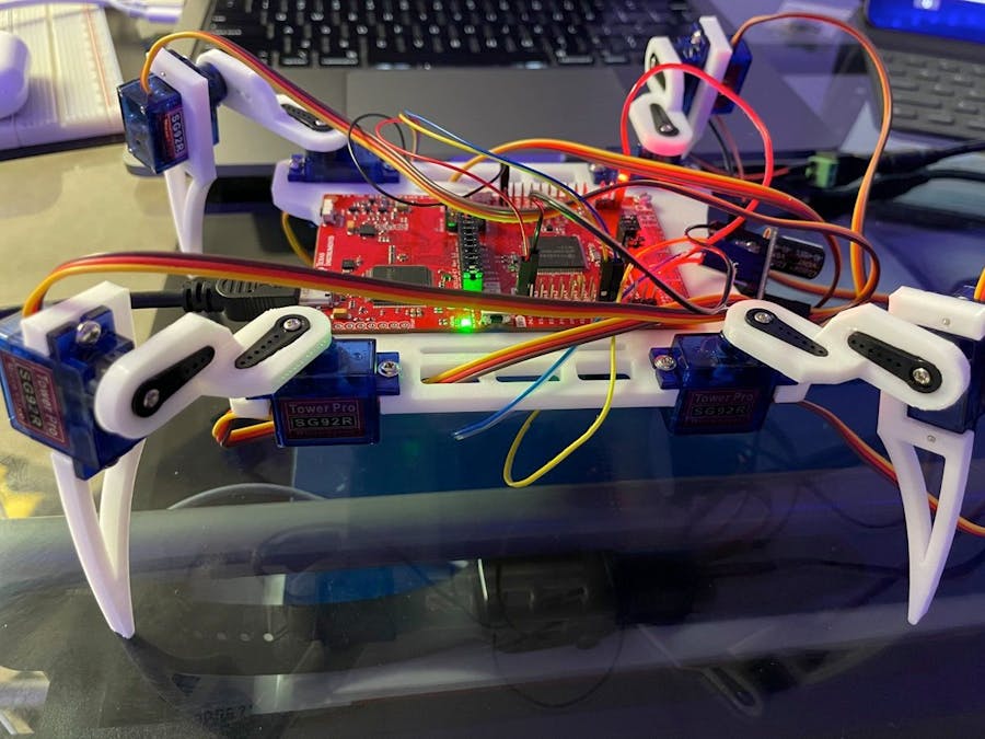
The goal for this project is to be able to design and build a "Roomba" type functional robot. This is achieved by using a MSP 432 board along with an ultrasonic distance sensor to influence the robot's movement. In order to power the robot, Quade, a 7.4V lipo battery will be used. In order for this battery to interface with all of the other components a voltage regulator will be necessary to ensure circuit protection. Two boards will be implemented into Quade: the MSP 432 and a PCA9685. The MSP will be used for interfacing with our IMU, Ultrasonic Distance Sensor, as well as outputting to our two LED's. The PCA board will be used for controlling the eight servos that will be used to create Quade's movement.
Movement ImplementationThe ultrasonic distance sensor will be capturing the distance away Quade is from the nearest obstacle or object. Using this data we will then program Quade to decide on what to do next. Quade will continue forward until the object is within the closest desired range. After this distance away is read, Quade will re-position himself to the right and take another scan using the sensor. If there are no obstacles within the lowest distance range, Quade will continue forward on the new path. If there is an object in the range, Quade will reposition again to the right and take another measurement. This process will repeat creating a "roomba" style automated robot. Depending on the type of movement Quade is making, the MSP will display a different color of LED. For example, if Quade is making a turn due to an obstacle detected the RED LED will blink. If Quade is moving directly forward as normal, the GREEN LED will blink.
Struggles & ChallengesInitially, as a group we planned on implementing the Ultrasonic Distance Sensor into our robot's design as well as using the lipo battery in order to create a fully "remote" robot. Due to time limitations we were only able to implement Quade's movement through a button interrupt. When the button was pressed, the interrupt was triggered changing the state of Quade to a forward motion as seen in the included video. In the future, with more time of course, we would implement our distance sensor to trigger this interrupt to change states only when an object was detected to be within 6 inches. This new state change will be triggered in order to execute a turning movement by Quade in order to avoid collisions.
Future DevelopmentA "creep gait" was in development for Quade but unfinished. This gait would have operated by lifting one leg and rotating it forward while each other leg slowly rotated backwards, and this would repeat for each leg. The code was developed but not fully implemented. This is due to unforeseen difficulty in determining the required angles
The design of a remotely powered Quade was created but not implemented as well. This involved using a 7.4V LIPO battery and a voltage divider in order to step down the voltage to the necessary 5V needed by the MSP432. The MSP would then be able to power the PCA board as well as the servos. Due to lacking the necessary adaptor to connect the voltage divider circuit to the MSP usb outlet, this addition was never implemented.
Functional Block DiagramTop Level Software Diagram:
LEDSoftware Diagram:
PCA to Servos Software Diagram:
IMUSoftware Diagram:
Operational Requirements:
- Quade shall recognize an obstacle within 6 inches of itself
- Quade shall move forward autonomously
- Quade shall re-position itself to the right when an obstacle is detected
- Quade shall evaluate the new position for obstacles before moving forward or re-positioning itself again
- Quade shall blink a green LED while moving forward
- Quade shall blink a red LED while turning
Physical Requirements:
- Each servo shall supply up to 1200 g-cm of torque
- Quade shall be stable, i.e the center of mass shall lie within the footprint while idle or moving
Power Requirements:
- Quade shall be powered using an on-board battery
- The MSP432R shall be supplied with 5V
- Each servo shall be supplied with 5V
- Each servo shall be supplied with a maximum current of 494.32 mA
- The 7.4 V supply shall be converted to 5V
- The ultrasonic sensor shall be supplied with 5V
- The ultrasonic sensor shall be supplied with 15 mA
- The IMU shall be supplied with 3.3V
- The IMU shall be supplied with 0.55 mA
- The PCA board shall be supplied with 3.3V
Sensor Requirements:
- The ultrasonic sensor shall receive a 10mu wave to the ECHO pin to trigger the sensor
- The ultrasonic sensor shall return a wave with range in proportion
- The MSP432R shall convert time received from the ultrasonic sensor and return distance
- The MSP432 shall communicate with the IMU via I2C
- The SCL frequency for the MSP432 and the IMU shall be between 0 and 100 kHz
Unit Test for Motor Control of 2 Servos
Magnetometer Output Verification Test:
In order to ensure Servo movement, individual testing of each component was needed in order to ensure the correct outcome. In the figure above, it is shown through the debugger that the magnetometer is successfully connected and is communicating with the MSP401R board.
I2C Communication with the Magnetometer:
Although the magnetometer was confirmed to be communicating via I2C with the MSP, when the SDA and SCL busses were connected to the AD2, the logic was unable to be read. Instead of clear start bits, data bits, and acknowledgment bits, the Waveforms software read errors. This was unexpected, and debugging attempts produced no results. This will require further investigation.
Debugger Interrupt triggered when button S1 is Pressed:
The next part of the necessary testing was to verify that the button-triggered interrupt was working. In the figure above you can see the button being pressed and in the debugger, the interrupt is triggered and the servo code is executed.
Complete Circuit for Servo Unit Test:
The figure above shows the complete circuit for the 2 servo unit test. All together there are 5 components. The IMU is connected to the MSP through pins 1.6 and 1.7. The PCA is also connected to those same pins and has a power and ground connection to the MSP board. Finally, there are two servos (simplified from 8 for testing) connected to the PCA board. The additional power connection is coming from a 10A 5V power supply which is connected to the PCA board in order to supply the additional voltage needed to move the servos.
Trade StudySensor for Movement Control Trade Study
This is the first Trade Study conducted in order to determine the best/most feasible way to create Quade's movement. We looked at three options: Infrared, an ultrasonic, and laser distance sensors. The criteria we used to rank the three methods are the time/difficulty to implement, cost, and functionality. This was conducted on a scale from 1 to 5 with 1 being the worst and 5 being the best.
Infrared Distance Sensor: 10
Time/Difficulty to Implement: 3
We have never used an infrared sensor before, so we would need to learn how it works, but it is compatible with the MSP432.
Cost: 3
The cost for an infrared distance sensor from adafruit is $14.95.
Functionality: 4
It is a short range distance sensor that uses infrared light to determine the distance of an object. It can be used at any time of the day, and can detect objects with more complex surfaces.
Ultrasonic Distance Sensor: 13
Time/Difficulty to Implement: 4
We have already worked on a project using the ultrasonic distance sensor, so we are familiar with how it works, meaning it should be easier to implement.
Cost: 5
This did come from our course kit, so there was no extra cost for group members, although it does costs $3.95 from Sparkfun.
Functionality: 4
It is a short range distance sensor that uses sound waves to determine the distance of objects in its vicinity. Because it uses sound waves, Quade can be used during anytime of the day in almost any environment. It does have trouble detecting objects with extreme surfaces, but we don't expect to run into object like that. Also, The application of our project doesn't require long range object detection.
Laser Distance Sensor: 9
Time/Difficulty to Implement: 2
We have never used a LiDAR sensor before, so we would need to learn how to use it, but it is compatible with the MSP432.
Cost: 2
The lowest cost for a LiDAR sensor we could find is $39.95 from Seeed Studio.
Functionality: 5
It is a long range distance sensor that uses a laser to determine the distance of an object. It is very accurate and can check for objects at a high frequency, so it can detect fast moving objects. LiDAR can be used day and night, and because of its shorter wavelength, it can detect smaller objects.
Under these conditions we determined that the best fit for our movement implementation of Quade was to use an ultrasonic distance sensor.


Comments