

Hardware components | ||||||
| × | 1 | ||||
| × | 1 | ||||
Software apps and online services | ||||||
 |
| |||||
nanoFramework Driver for the 74HC595 Shift Register
Shift Register Tutorial
Read moreSource Code :https://github.com/Dweaver309/Shift-Register-74HC595/tree/Source_Code
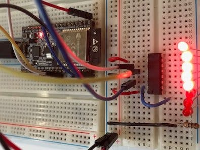
74HC595 shift register enables up to 8 additional output ports using only three ports from the device. More ports can be added by "daisy chaining" more chips.
The hardware- The Q0 to Q7 pins are the new output pins they are in reverse order Q7 is Pin 0 and Q0 is Pin 7
- VCC is connected to 3.3 volts or 5 volts
- Data, Latch, Clock are connected to any three digital pins
- Output Enable is connected to ground
- Master Reset is connected to VCC
- GND is connected to ground
- The driver is first initialized by calling the constructor like this:
HC595 ShiftRegister = new HC595(Clock, Data, Latch)
- The pin state is changed by the method SetPin:
SetPin(Pin,State) Example: ShiftRegister.SetPin(7, false)
1. The SetPin method sets the "Latch" pin low
2. Changes the Bit array to the current state
3. Loops through each bit and sets the data pin high for 1 and low for 0
4. Pulses the Clock pin high and then low to send the data to the shift register
5. After looping though the 8 bits of data the "Latch" pin is pulled high to activate the shift register pins to the current bits state
Contributor: David Weaver

Thanks to David Weaver.


Comments