
Hardware components | ||||||
_baVEVgguW1.jpg?auto=compress%2Cformat&w=48&h=48&fit=fill&bg=ffffff) |
| × | 1 | |||
Software apps and online services | ||||||
 |
| |||||
| ||||||
Arduino101 is a powerful board with builtin BLE communication, but due to the lack of BLE standards it is difficult to get a general purpose control app without a lot of Android programming.
This project provides a complete sketch that allows each digital pin to be configured and controlled and each analog input pins value displayed. The sketch is designed to talk to pfodApp but none of the display or user interaction shown here is hard coded into pfodApp. Once you have finished this project you can design your own menus and controls working with the same pfodApp
Quick StartUpdate: V1.8.2 and Curie V2.0.2 looses BLE connections when trying to load the drawing. IDE V1.8.2 and Curie V1.0.7 works stably. See the bottom of this project for how to downgrade your Arduino101 to V1.0.7
1) Download and install Arduino IDE V1.8.2 from http://arduino.cc/en/Main/Software. That web page has links for various operating systems and a link to GettingStarted (http://arduino.cc/en/Guide/HomePage). Go through the GettingStarted steps for your operating system at the end of which you will have uploaded the BLINK program to your Arduino101 board.
2) Download the latest pfodParser library V3.4+ and pfodDwgControls library. Follow the instructions on that page for installing it. Delete any previous pfodParser library dir first.
3) Download the Arduino101Starter.zip and unzip it to your Arduino sketch directory. It will unzip an Arduino101Starter directory. Open Arduino101Starter.ino and compile and download to your Arduino101.
4) Download and install pfodApp V3.0.307+ on your Android mobile (Android V4.4.1 and above for BLE support). Follow the pfodAppForAndroidGettingStarted.pdf to pair your mobile with the Bluetooth Shield and setup a new pfodApp connection, I called mine “101”.
5) Finally click on your 101 connection to connect to your Arduino101 board via bluetooth low energy (BLE). The Arduino101Starter sketch will progressively load this dwg.
Click on the area of the board you want to work with to zoom in.
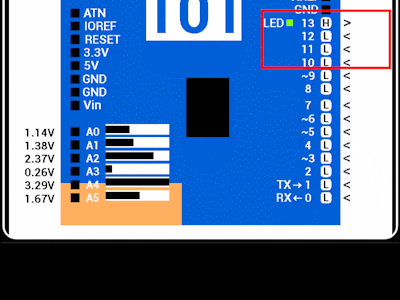
Then click the Digital pin you want to configure.
Pins with ~ symbol can be configured as PWM outputs.
Analog pins are not configurable and are updated with the current reading when you are don't have the zoom window open. The ? button provides brief on screen help. The x button closes the window.
Next StepsNone of these displays are hard coded into pfodApp. The board outline, the zoom square that you can drag around with your finger, the zoom window, the pin selection and configuration are all completely controlled by the sketch loaded in your Arduino101.
This means you have complete control over what is presented to the user and how they interact with it.
The free pfodDesigner app lets you design your own menu system and then generates the necessary code for Arduino101 and many other boards/shields.
You can also add your own custom graphical controls, like the one above, to your menu system. See Custom Arduino Controls for Android for a general introduction to creating custom controls.
How to downgrade Arduino101 from Curie V2.0.2 to V1.0.7Unplug your Arduino101 board (important!) Open the Tools -> Board Manager and search for Curie and REMOVE it. Then open Tools -> Board Manager and search for Curie and click more Info and choose V1.0.7 to install. Plug your Arduino101 board back in. Wait for the USB drivers installation to complete.
- Open Tools -> Board and select Arduino101
- Open Tools -> Programmer and select Arduino/Genuino 101 Firmware Updates
- Select Tools -> Burn Bootloader. This may appear to hang at 0% for some time before jumping to compete
Unplug your Arduino101 board (very important!!) Plug the board back in. Program the Arduino101Start.ino sketch. I got this error message at the end:
SUCCESS: Sketch will execute in about 5 seconds.
Exception in thread "Thread-22" java.util.ConcurrentModificationException
But got SUCCESS and the sketch worked with out failing.


Comments