

![xyz-mIoT by itbrainpower.net [ARM0 + BG96 (LTE CATM1+NB IoT+2G modem +GNSS), no embedded sensors]](https://hackster.imgix.net/uploads/attachments/938033/xyz-miot-bg96_880px_rnVWepIwic.jpg?auto=compress%2Cformat&w=48&h=48&fit=fill&bg=ffffff)
![xyz-mIoT by itbrainpower.net [ARM0 + BC95G (NB IoT modem), no embedded sensors]](https://hackster.imgix.net/uploads/attachments/932249/xyz-mIoT-BC95G_880px.jpg?auto=compress%2Cformat&w=48&h=48&fit=fill&bg=ffffff)
![xyz-mIoT by itbrainpower.net [ARM0 + M95FA (2G modem), no embedded sensors]](https://hackster.imgix.net/uploads/attachments/938035/xyz-miot-m95fa_880px_ScqANEUjvg.jpg?auto=compress%2Cformat&w=48&h=48&fit=fill&bg=ffffff)
![xyz-mIoT by itbrainpower.net [ARM0 + LiPO charger, no modem, no embedded sensors]](https://hackster.imgix.net/uploads/attachments/1082044/no_modem_raw_transparent_sjihf5OmqC.jpg?auto=compress%2Cformat&w=48&h=48&fit=fill&bg=ffffff)

Microchip SAMD21G is a very powerful ARM0 MCU included in Arduino Zero, xyz-mIoT by itbrainpower.net and similar boards.
Even the MCU itself is quite powerful and versatile, when used with Arduino IDE, the MCU consumption in DEEP sleep mode is significant ~0.75 - 2.5mA - depending on board used and also dependent on MCU modules [Serial/Serial1/I2C/oscillators...] enabled by software application. This known limitation makes successful SAMD21G shields, as the one mentioned before, not to be the first choice for low power battery operated projects.... until now!
In this tutorial, I will show you what should be done to decrease the xyz-mIoT SAMD21G deep sleep mode power consumption, from 1-2mA down to a decent 35-37uA*.
* for sensor-less xyz-mIoT by itbrainpower.net shields versions, including BG96, BC95G, M95FA modems and modem-less versions. For xyz-mIoT shield versions populated with sensors, all measured current values will be slightly higher.
* RTCC based and 1 pin interrupt wake up from deep sleep mode. * precision crystal 32.768kHz oscillator [XOSC32K] is maintained in deep sleep for time accuracy.
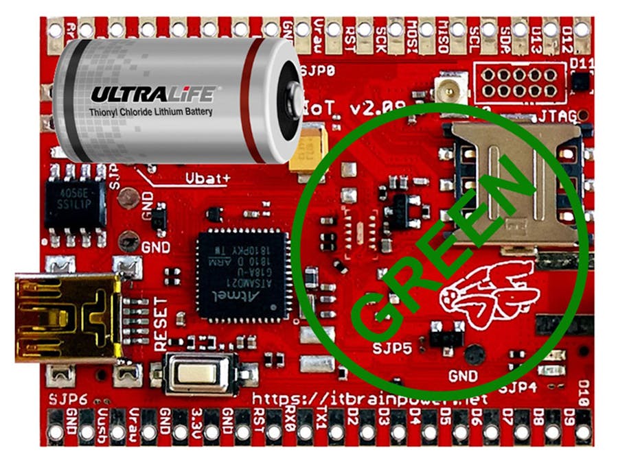
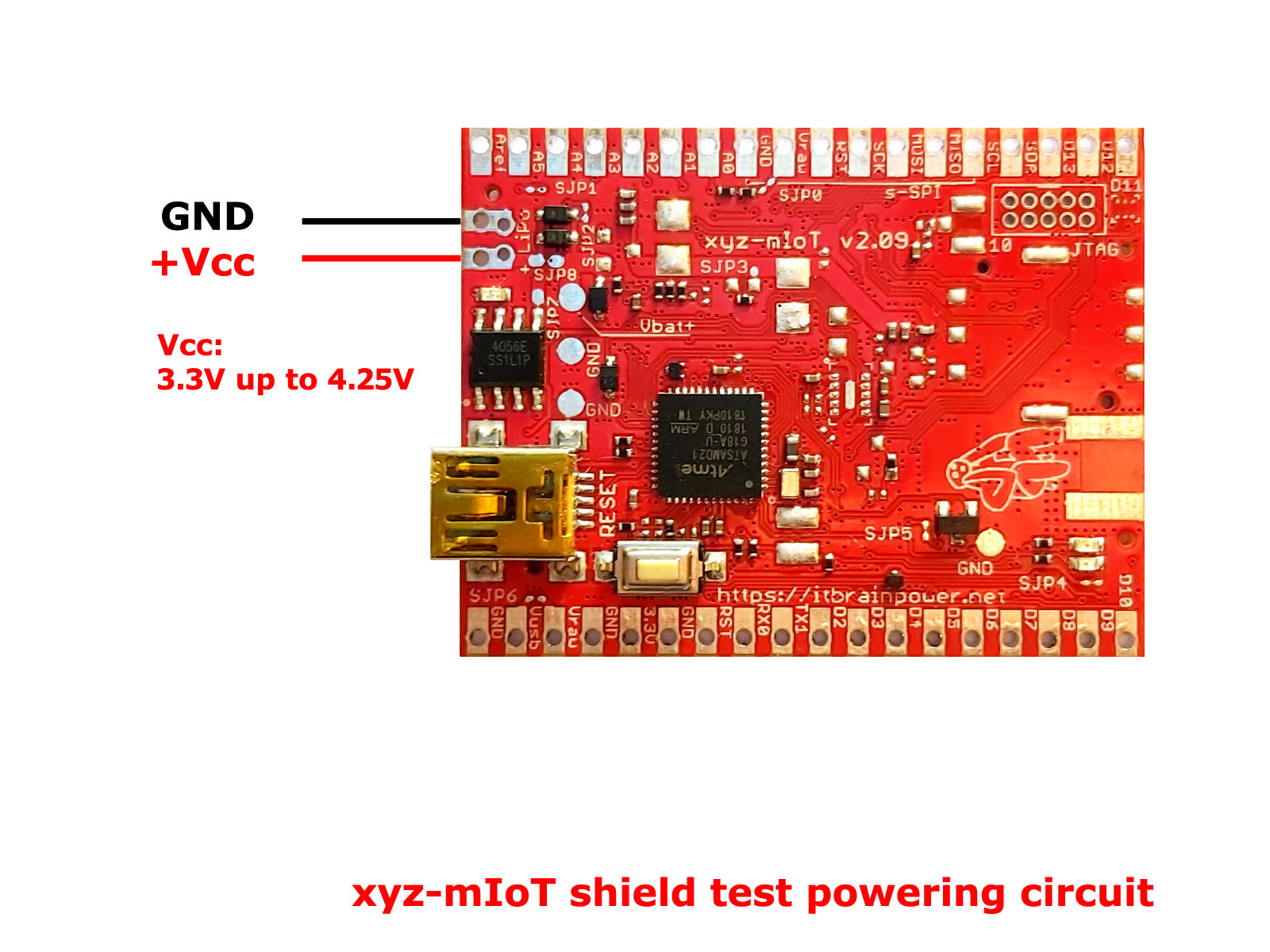
* embedded xyz-mIoT LDO was not bypassed - shield was powered via LiPO pads (Vbat and GND pins) at voltages between 3.3V and 4.2V.
* current measurements was performed, as global shield consumption, at 25degrees Celsius with all shield power supply chain (LiPO, LiION charger, LDO,...) maintained.
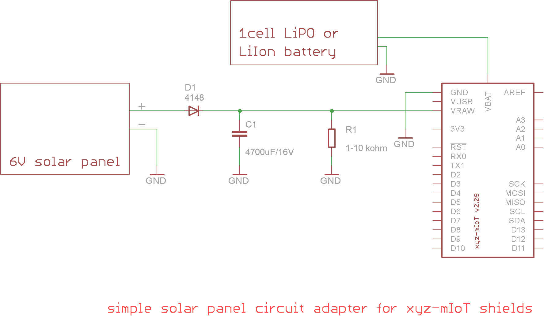
Methods that are about to be reaveled in this article may be applied for battery powered, solar powered xyz-mIoT shields and also for classic wall powered solutions in order to decrease total IOT node power requirements.
Your IoT device will last for years powered by LiPO, LiION or Lithium batteries.
Highlights and references about xyz-mIoT shieldsxyz-mIoT by itbrainpower.net is a 35x45mm IoT shield built around ATSAMD21G ARM0 micro-controller (Arduino Zero compatible design) having embedded LiPO battery charger module, optional embedded THS + tVOC + HALL + IR +tilt/vibration sensors and optional LowPower LTE CATM1 or NB-IoT, 3G or GSM modem.
As modem capability classification, four main variants are commercially available right now:
- one equipped with M95FA [2G worldwide modem],
- one equipped with BC95G [low power NB IoT worldwide modem],
- one populated with BG96 [low power LTE CATM1 + NB IoT + EGPRS worldwide modem + GNSS] and
- one bare-bone variant [w/o modem - intended for IoT solution based on external Ethernet/WIFI/LORA communication modules].
On demand, variants equipped with LTE CAT4, LTE CAT1 or 3G and with features as embedded SIM may be provided to system integrator partners.
xyz-mIoT hardware references
- xyz-mIoT shield - specifications and PN coding
- xyz-mIoT shield - pinout, port map and more
- xyz-mIoT shield - block schematics
- Microchip/Atmel ATSAMD21G - ARM0 micro-controller datasheet
- other documentation, as: modems specification and AT manual, sensors datasheets, xyz-mIoT mechanical drawing and more.
- xyz-mIoT SPI integration examples [ILI9341 240x320 TFT and SD reader].
- xyz-mIoT UART0 integration example - [ESP12F - ESP8266MOD WIFI shield by AI-THINKER].
- xyz-mIoT GPIO usage example - [SMS Relay controller].
- and
- xyz-mIoT powering reference.
Default voltage used in test measurements was 3.8V. Test circuit as bellow, milli / micro-ampermeter placed in series on Vbat wire.
In image above is represented xyz-mIoT bare-bone variant [no modem], PN: XYZMIOT209#NOMODEM-000-0000000, but similar consumption results was obtained for xyz-mIoT shields variants mentioned above.
RTCC SLEEP ALARM - Software for default run / sleep consumption tests
We used a slightly modified version of RTCC sleep alarm example available in RTCZero library, in order to be able to determine the SAMD21G consumption in SLEEP / RUN mode having, or not, Serial and Serial1 modules enabled.
/* standard RTC sleep for SAMD21G, adapted for xyz-mIoT / SAMD21G current consumption measurements in RUN / SLEEP modes
 *
 * a. test without Serial and Serial1 software modules loaded
 * b. test with Serial and Serial1 software modules loaded - remove comments on lines 52 and 53
 *   Dependencies:
 *	- SAMD21G RTCC library from https://itbrainpower.net/downloads#xyz-mIoT
 *
 *
 * Dragos Iosub, Bucharest 2020.
 * https://itbrainpower.net
 */

  /*
  Sleep RTC Alarm for Arduino Zero

  Demonstrates the use an alarm to wake up an Arduino zero from Standby mode

  This example code is in the public domain

  http://arduino.cc/en/Tutorial/SleepRTCAlarm

  created by Arturo Guadalupi
  17 Nov 2015
  modified
  01 Mar 2016

  NOTE:
  If you use this sketch with a MKR1000 you will see no output on the serial monitor.
  This happens because the USB clock is stopped so it the USB connection is stopped too.
  **To see again the USB port you have to double tap on the reset button!**
*/

#include <RTCZero.h>

/* Create an rtc object */
RTCZero rtc;

/* Change these values to set the current initial time */
const byte seconds = 0;
const byte minutes = 00;
const byte hours = 17;

/* Change these values to set the current initial date */
const byte day = 17;
const byte month = 11;
const byte year = 15;

void setup()
{
  delay(5000);
  pinMode(LED_BUILTIN, OUTPUT);
  digitalWrite(LED_BUILTIN, LOW);

  //Serial.begin(9600);
  //Serial1.begin(9600);

  rtc.begin();

  rtc.setTime(hours, minutes, seconds);
  rtc.setDate(day, month, year);

  rtc.setAlarmTime(17, 00, 10);
  rtc.enableAlarm(rtc.MATCH_HHMMSS);

  rtc.attachInterrupt(alarmMatch);

  rtc.standbyMode();
}

void loop()
{
  //blink once, show me MCU is in RUN mode
  delay(500);
  digitalWrite(LED_BUILTIN, LOW);
  delay(500);
  digitalWrite(LED_BUILTIN, HIGH);
  delay(500);
  digitalWrite(LED_BUILTIN, LOW);

  delay(5000);								// intended for current consumption in RUN mode

  //blink twice, show me the MCU will enter SLEEP mode
  digitalWrite(LED_BUILTIN, HIGH);
  delay(500);
  digitalWrite(LED_BUILTIN, LOW);
  delay(500);
  digitalWrite(LED_BUILTIN, HIGH);
  delay(500);
  digitalWrite(LED_BUILTIN, LOW);


  rtc.setTime(hours, minutes, seconds);
  rtc.setDate(day, month, year);

  rtc.standbyMode();    					// Sleep until next alarm match, now you may sample the sleep current
}

void alarmMatch()
{
  digitalWrite(LED_BUILTIN, HIGH);
}
Download above code (right click and save as) from: standardRTCSleepAlarm.ino. Use our patched SAMD21G RTCC library inside "xyz-mIoT shields RTCC and WDT Arduino classes" package, from: xyz-mIoT downnload page.
Standard power profile - no optimizations:
a. RUN mode, no UARTs enabled: 10.02 mA
b. RUN mode, both UARTs enabled but idle: 11.38 mA
c. SLEEP mode, no UARTs enabled / both UARTs enabled: 750uA / 1310uA.
Shield USB must be not connected! Even this is not activated in software, USB will contribute with minimum 400uA at total shield consumption!
At this point we have some references about SAMD21G, together with xyz-mIoT module and interfaces, consumption - partial caused by hardware, but partial caused by Arduino IDE handling of ARM modules. Next, let do the magic!
Optimization step 1 - patch the hardware around SAMD21GHINTS:
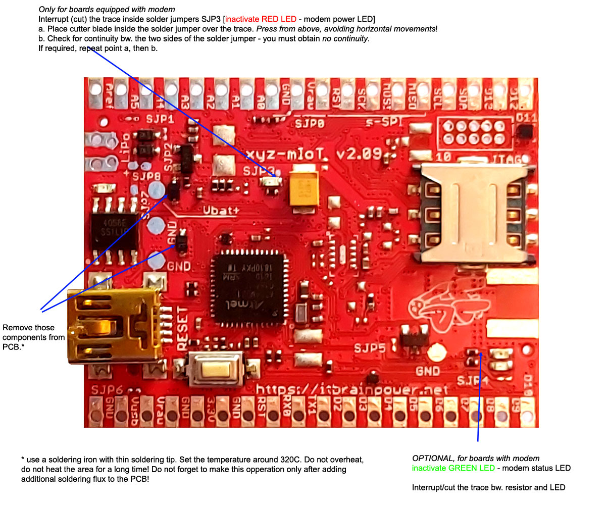
- If your xyz-mIoT shield have the P/N with "-LPR" suffix (Eg.: "XYZMIOT209#M95FA-UFL-0000000-LPR") skip hardware preparation step and go directly to SAMD21G optimized low power software section.
- If you are not sure about board PN, just identify if your board is populated with components marked as: "Remove those components from PCB" in Image 2. If both protection diodes are NOT populated, your xyz-mIoT shield meet the low power criteria and you may like to go directly to SAMD21G optimized low power software section.
Using a soldering iron with proper thin tip, remove the protection diodes marked as: "Remove those components from PCB" in Image2. Set solder iron temperature around 320C. Add soldering flux to designated PCB areas before applying the soldering iron to PCB. A pincers with fine tips will be quite helpful.
This operation will be reflected in 200-250uA spared current consumption in SAMD21G SLEEP mode.
Other operations showed in Image 2 are related only to xyz-mIoT with modem variants and will be reflected in consumption decrease only in RUN mode with modem enabled. I recommend NOT to inactivate the LEDs before you finish your project development phase! ;)
After applying basic hardware patches, let run again above standardRTCSleepAlarm.ino and to measure again the current consumption. We obtained following values:
a. RUN mode, no UARTs enabled: ~9.67mA
b. RUN mode, both UARTs enabled but idle: ~11.00mA
c. SLEEP mode, no UARTs enabled / both UARTs enabled: 457uA / 1125uA
Better? Better, but not the best. Let go to optimized software section!
Optimization step 2 - Optimized low power mode softwareThe principles behind the optimized software [and implemented in library]:
a. just WAKE as less as necessary resources [eg.: Serial],
b. before SLEEP free the resources [ARM module, assigned oscillator, GPIO mux,...] waked and used in RUN mode,
c. patch some resources started by default by Arduino IDE.
/*
  SAMD21G optimized SLEEP software w. Serial and Serial1 activated for xyz-mIoT by itbrainpower.net shields.
  version 0831c / 2020.02.29

  RTCC [w. wake at each 30secs - see reloadRTCC() function] and D7 as interrupt on LOW level detection wake up!

  Serial and Serial1 load/unload procedures for low power mode!
  Crystal 32.768kHz precision oscillator [XOSC32K] was mentained for SLEEP.

  WARNING:
	- use patched RTCC library from https://itbrainpower.net/downloads#xyz-mIoT
	- disconnect USB from shield. Else, even not enabled, the consumption will be highier w. minimum 400uA
	- debug messages are provided via Serial1 --> connect 3.3V UART - USB adapter to xyz-mIoT shield RX0, TX1 and GND pads!!

  Dependencies:
	- SAMD21G RTCC library from https://itbrainpower.net/downloads#xyz-mIoT
	- xyz-mIoT LowPower library from https://itbrainpower.net/downloads#xyz-mIoT


  SLEEP consumption ~ 34-37uA powered bw. 3.3-4.1V* via LiPO pads* [Vbat and GND]. This should cover scenarios as powering from:
		- LiPO, LiION rechargeable batteries [charging mechanism is mentained]
		- Lithium primary batteries

  itbrainpower.net invests significant time in design phase of our IoT products and in associated software and support resources.
  Support us by purchasing our IOT modems, IOT shields and sensors from here https://itbrainpower.net/order

  Enjoy!

  Dragos Iosub, Bucharest 2020.
  https://itbrainpower.net

 */

#include <xyz-mIoT_LowPower.h>

#include <RTCZero.h>

RTCZero rtc;

#define contactIN   7 							//digital port used for wake up (...and having embedded weak pullup resistor, see docs)

#define RTCINT      1
#define GPIOINT     2

/* Change these values to set the current initial time */
const byte seconds = 0;
const byte minutes = 00;
const byte hours = 17;

/* Change these values to set the current initial date */
const byte day = 17;
const byte month = 11;
const byte year = 15;

int interruptMode = 0;


void setup()
{
  delay(5000); 									//do not remove this, else you may not be able to program the shield!!!!!

  interruptMode = 0;

  xyzmIoTLowPower.begin();

  xyzmIoTLowPower.ledBLINK(500,1);

  //SerialUSB.begin(115200);
  xyzmIoTLowPower.loadSerial();					//modem UART
  xyzmIoTLowPower.loadSerial1();				//external UART

  Serial1.println("test LPR");

  rtc.begin();

  rtc.attachInterrupt(RTCCalarmEvent);

  initWakePin();
  xyzHibernate();
}

void loop()
{
  //SerialUSB.begin(115200);
  xyzmIoTLowPower.loadSerial();					//modem UART
  xyzmIoTLowPower.loadSerial1();				//external UART

  switch(interruptMode)
  {
     case(RTCINT):
        Serial1.println("RTC interrupt");

        xyzmIoTLowPower.ledBLINK(500,2);
     break;
     case(GPIOINT):
        Serial1.println("GPIO interrupt");

        xyzmIoTLowPower.ledBLINK(100,3);
        delay(1000);
        xyzmIoTLowPower.ledBLINK(100,3);
     break;
     default:       //never here
     break;
  }

  xyzHibernate();
}


void reloadRTCC()
{
  rtc.setTime(hours, minutes, seconds);
  rtc.setDate(day, month, year);

  rtc.setAlarmTime(17, 00, 30);
  rtc.enableAlarm(rtc.MATCH_HHMMSS);
}


void RTCCalarmEvent() 						//this is RTCC interrupt routine
{
  interruptMode = RTCINT;
}

void initWakePin()
{
  pinMode(contactIN, INPUT);                //default, D7 have a weak pullup embedded (10Mohms) - read xyz-mIoT documentation
  attachInterrupt(contactIN, digitalINalarmEvent, LOW);
}


void digitalINalarmEvent()					//this is GPIO interrupt routine
{
  interruptMode = GPIOINT;
}


void xyzHibernate(void)
{
  interruptMode = 0;
  reloadRTCC();
  xyzmIoTLowPower.xyzSleep();
}
What this software does:
- enable SAMD21 SLEEP with wake driven by RTCC at each 30secs [reloadRTCC() function] and waked by D7 as interrupt on LOW level detection.
- detect the WAKE interrupt type [RTCC or GPIO],
- signalize leaving SLEEP mode by D13 embedded LED [yellow]
- in RUN mode, both Serial and Serial1 are enabled.
Our measurement results for optimized SLEEP code:
a. RUN mode, both UARTs enabled: 10.23mA
b. SLEEP mode: 35uA
Download above code (right click and save as) from: optimized_SAMD21G_SLEEP_RTCC_IN_INTERRUPT_0831c.
Download and install "xyz-mIoT LowPower library" class, from: xyz-mIoT download page.
Download and install SAMD21G RTCC library inside "xyz-mIoT shields RTCC and WDT Arduino classes" package, from: xyz-mIoT download page.
Compile the code, upload it to xyz-mIoT and remove USB cable. Now you will be able to measure the current consumption.
Yellow LED will blink once/twice when SAMD21G will enter ACTIVE mode and will blink 4 times before enter SLEEP mode.
HINTS:- Shield USB must be not connected! Even if is not activated in software, USB will contribute with minimum 400uA at total shield consumption!:- Serial1 it is used as debug port. To visualize the debug messages, just connect one 3.3V compliant USB-UART adapter to RX0 and TX1 pins.
Enjoy!
TUTORIAL PROVIDED WITHOUT ANY WARRANTY!!! USE IT AT YOUR OWN RISK!!!!
itbrainpower.net invests significant time in design phase of our IoT products and in associated software and support resources. Support us by purchasing our IOT modems, IOT shields and sensors from here https://itbrainpower.net/order


Comments