
Hardware components | ||||||
| × | 1 | ||||
| × | 1 | ||||
| × | 4 | ||||
| × | 2 | ||||
| × | 1 | ||||
| × | 2 | ||||
| × | 1 | ||||
| × | 3 | ||||
 |
| × | 1 | |||
| × | 2 | ||||
| × | 2 | ||||
| × | 7 | ||||
| × | 6 | ||||
| × | 3 | ||||
| × | 2 | ||||
| × | 5 | ||||
| × | 1 | ||||
Software apps and online services | ||||||
 |
| |||||
Hand tools and fabrication machines | ||||||
 |
| |||||
 |
| |||||
NOTE:If you are here looking for information about the Jacob's Ladder in the cover video, it is a kit from Amazon - Jacob's Ladder Kit. It needs an external bench power supply to make it work!
IntroductionThis project started with a big heavy 10 amp 24 volt transformer. I bought it to experiment with inverters, but it worked very poorly as an inverter. So I decided to use it for a power supply. The result is probably overkill. "The Beast" is like the "Abrams Tank" of power supplies! It's heavy and capable of delivering 240 watts of power in almost any combination of voltage and current you can think of.
It's actually three power supplies in one: two 10 amp 2-30 volt power supplies and one 1 amp 3-30 volt plus / minus dual supply. If you build it, it will meet all your bench power supply needs forever! Alternatively, this project could be a template for any number of smaller, cheaper power supplies using a smaller transformer and perhaps only a single output.
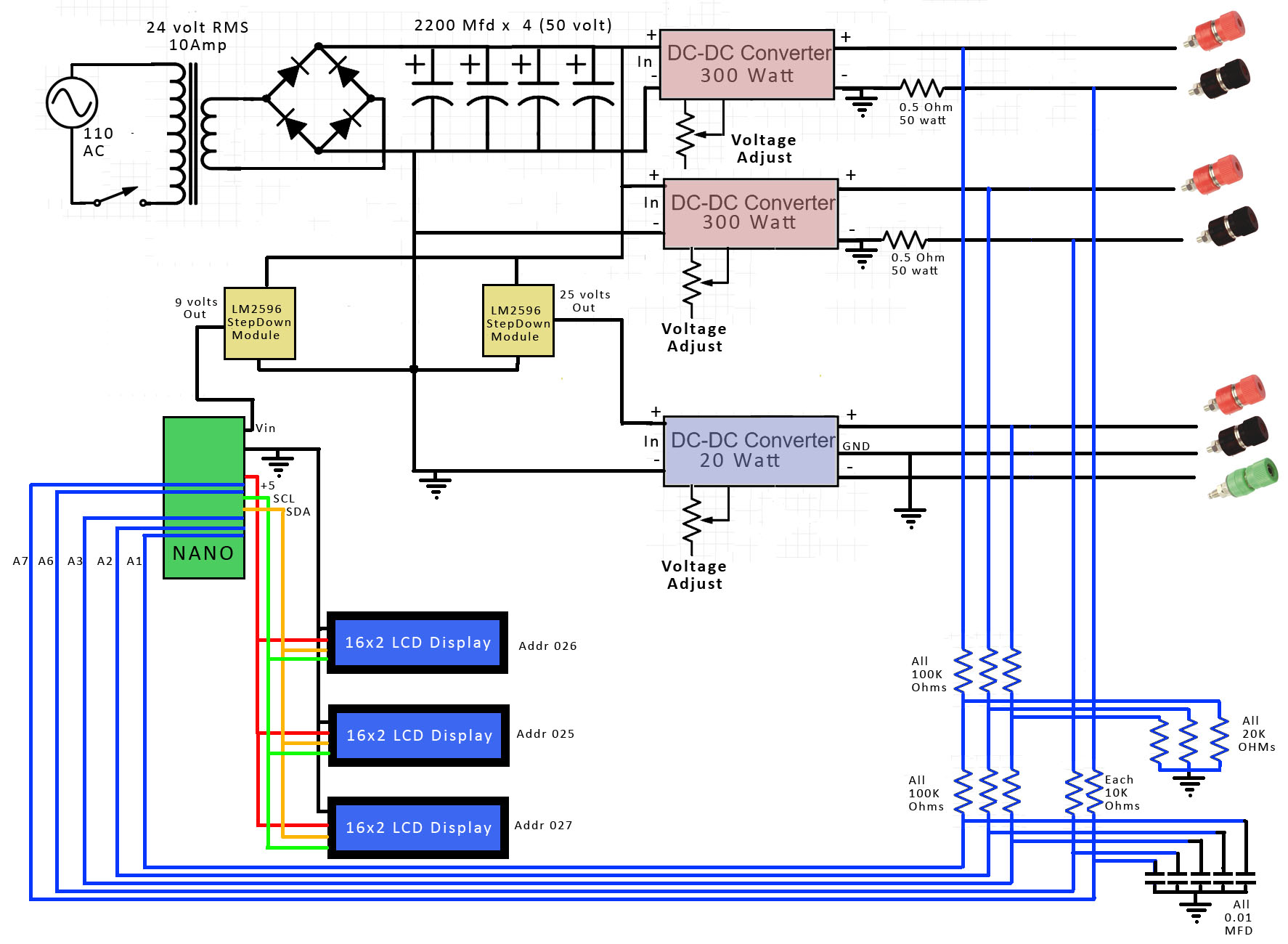
With so many inexpensive DC-DC converters available, I decided to combine some of them with this transformer to build the ultimate bench power supply. While I was at it, I decided to add some nice auxiliary stuff - voltage and current displays, precision potentiometers to set voltages, etc. I used an Arduino Nano to measure voltage and current. I display the results on three 16x2 LCD displays controlled with a single I2C interface.
Hardware DesignThe transformer itself is 10 amp, 24 volt RMS, with a peak voltage of 36 volts. After adding a full wave bridge and four 50 volt 2200 MFD electrolytic capacitors, we have a high current 36 volt DC supply as the starting point for everything else.
The main supplies are derived from 2 DC-DC 20 amp buck converters connected directly to the 36 volts. These converters' outputs can be set from 2-30 volts and are 95% efficient. I set their current limits to 10 amps each. The transformer has an overall rating of 240 watts (24 volts * 10 amps), so with both supplies set at 10 amps and 30 volts, we would be over the transformers rated output, but for most actual usage, we would be below 240 watts.
The other supply is a 20 watt ± 3-30 volt dual supply buck-boost converter. It is obviously much lower current than the main supplies, but can typically supply up to 1 amp both positive and negative voltage to power op amps, audio amps, etc. This supply has a maximum input voltage of 30 volts, so I used an LM2596 buck converter module to drop the input voltage down to about 25 volts.
I also used another LM2596 buck converter module to supply the power for the Arduino and LCD displays - set to 9 volts, it supplies the Arduino's Vin, while the displays run directly off the Arduino's +5v output.
We are sensing voltage for each of the 3 supplies through a 1/6 voltage divider, which for 30 volts puts a maximum of 5 volts into the Nano's analog input. Current sensing is done only for the two high current supplies, using 0.5 ohm, 50 watt resistors as current sensors. The voltage across those resistors is 5 volts at 10 amps, and the analog input can sense current down to 8 ma.
The external potentiometers I used are the same values as the small trim pots on the DC-DC converters - 100 K for each of the two high current converters and 50 K for the dual ± converter. The voltage trim pots on the converters have to be removed and replaced with the external ones. You should carefully de-solder them, then replace them with wires to the external precision potentiometers. You only need two wires to the potentiometer to change the voltage.
We are using three LCD displays on I2C, so the address of two of them needed to changed. That's done with a jumper on the backside of the display module. The default address is 027. By closing the A0 address shunt (as shown in the picture below), we change the address to 026, and by closing the second A1 instead, we get 025.
As the schematic shows, the circuitry for this power supply his fairly simple and straight forward. However, when you look at the finished product, with its multiple supplies and sensing circuitry, it has gotten very busy. We have a lot of stuff crammed into a fairly small space.
We haven't talked much about physical construction yet. The face plate is 3D printed, and I have included a .STL file for its construction. Normally, I might have 3D printed the bottom as well, but that 24 volt transformer is so heavy, I decided to use plywood, 3/8" or 1 cm. I could have build a complete case, but decided to just leave it open.
Almost everything is fastened down with hot glue. I ended up using a whole lot of it!
Most of the power handling wire is either bare 18 gauge tinned copper or stranded 16 gauge insulated "hookup" wire. For non-power wiring, I used Arduino breadboard wires or, in the case of those wires to the precision potentiometers, I used twisted pair copper telephone wire.
For hardware that looks pretty simple, construction turned out to be a little more complicated and problematic than I expected. Make sure everything that is suppose to be at ground really is at ground. Anything left floating will cause all kinds of mysterious, bewildering results!
Also, the precision pots are very sensitive to soldering iron heat, unlike most passive components. I overheated one, and it failed the next day. Running those 300 watt Buck converters close to their 40 volt maximum ended up causing a problem as well. When the potentiometer failed, it took one of my 300 watt converters with it. The converters go to their maximum output with no resistance at the potentiometer, and the converter failed shortly after the potentiometer did!
Needless to say, it took me a while to figure out what was going on with these component failures. So make sure the pot is connected and working properly before applying 36 volts to the converter's input.
SoftwareThe Arduino Nano program/sketch for this project is fairly simple. We are using the LCD_I2C library to control our three 16x2 LCD displays. The I2C interface uses pins A4 and A5 to control the displays. To sense voltages, we use 3 analog read pins: A1, A2, and A3. And to read currents, we use analog read pins: A6 and A7. With both voltage and current, we can calculate and display wattage.
The voltage we read on the Nano is the voltage between the high output and ground. For the two high current supplies, however, the negative output is actually slightly above ground, as a result of the current sensing 0.5 ohm resistor. We have also measured the voltage across this sense resistor, and so we subtract it from our voltage reading to get the actual voltage across the output posts.
One important caveat about these current measurements is that they only work as long as the negative output posts are allowed to float. They are slightly off ground. If you need to tie them all together to a common (true) ground, you can do that, but you bypass the current sensors in the process, so you will no longer be correctly measuring current or wattage.
Our power supply is an electrically noisy environment, so our ADCs or analog reads pick up some noise, especially at 0 current. Since we are subtracting the voltage drop across the current sensing resistor, noisy current readings also cause noisy voltage readings. Since we have lots of time to take analog reads, we take 32 reads and average them before updating the displays. This keeps the current reading at 0 when there is no load on the supplies.
Finally, for each of the 5 analog reads, the software includes a correction factor, which is currently set to 1 - i.e. no correction. The resistors I am using for measurements aren't precision, so If you really want to get precision readings of voltage and/or current, you can tweak these correction factors to make the display voltages and currents more accurate.
ConclusionsThe "Beast" turned out to be a little bit more complicated than I originally planned, but I think it came out as a good bench power supply, with lots of power and lots of flexibility.
Although I used that Jacob's Ladder in my cover video, it's current demands fluctuate wildly. The 300 watt buck converters didn't respond well to those fluctuations - they may have been tripping the current limit, because the voltage fluctuated a lot.
Finally, measuring the current with 0.5 ohm resistors causes a voltage drop of up to 5 volts across those resistors. Perhaps I should have used 0.1 ohm resistors and a processor with 14 or 16 bit Analog reads- voltage wouldn't have changed nearly as much in response to current changes.


Comments