
Hardware components | ||||||
 |
| × | 1 | |||
| × | 6 | ||||
| × | 1 | ||||
| × | 7 | ||||
| × | 7 | ||||
| × | 4 | ||||
| × | 7 | ||||
| × | 7 | ||||
| × | 7 | ||||
| × | 1 | ||||
| × | 1 | ||||
| × | 1 | ||||
| × | 2 | ||||
Software apps and online services | ||||||
 |
| |||||
Hand tools and fabrication machines | ||||||
 |
| |||||
 |
| |||||
 |
| |||||
Nixie tubes are quite popular with electronic hobbyists lately. They are an antique novelty! I am one of the few among us who is old enough to remember when Nixie tubes were state-of-the-art displays back in the 1960s and early 70s. They disappeared almost instantly with the arrival of LED displays!
Most of the Nixie projects I have seen here are expensive and use pre-assembled Nixie tube displays. My objectives in this project were to make it inexpensive and build it from scratch, so that I really knew how everything works! I wanted it to include seconds. I wanted it to include blinking colons. I wanted it to be configurable to a 12 or 24 hour clock. I wanted the finished product to look nice. And I wanted to do all that for about $100. So here is what I ended up with:
I came pretty close to my $100 cost goal. I have listed the prices in the comments on my parts list. They total $110!
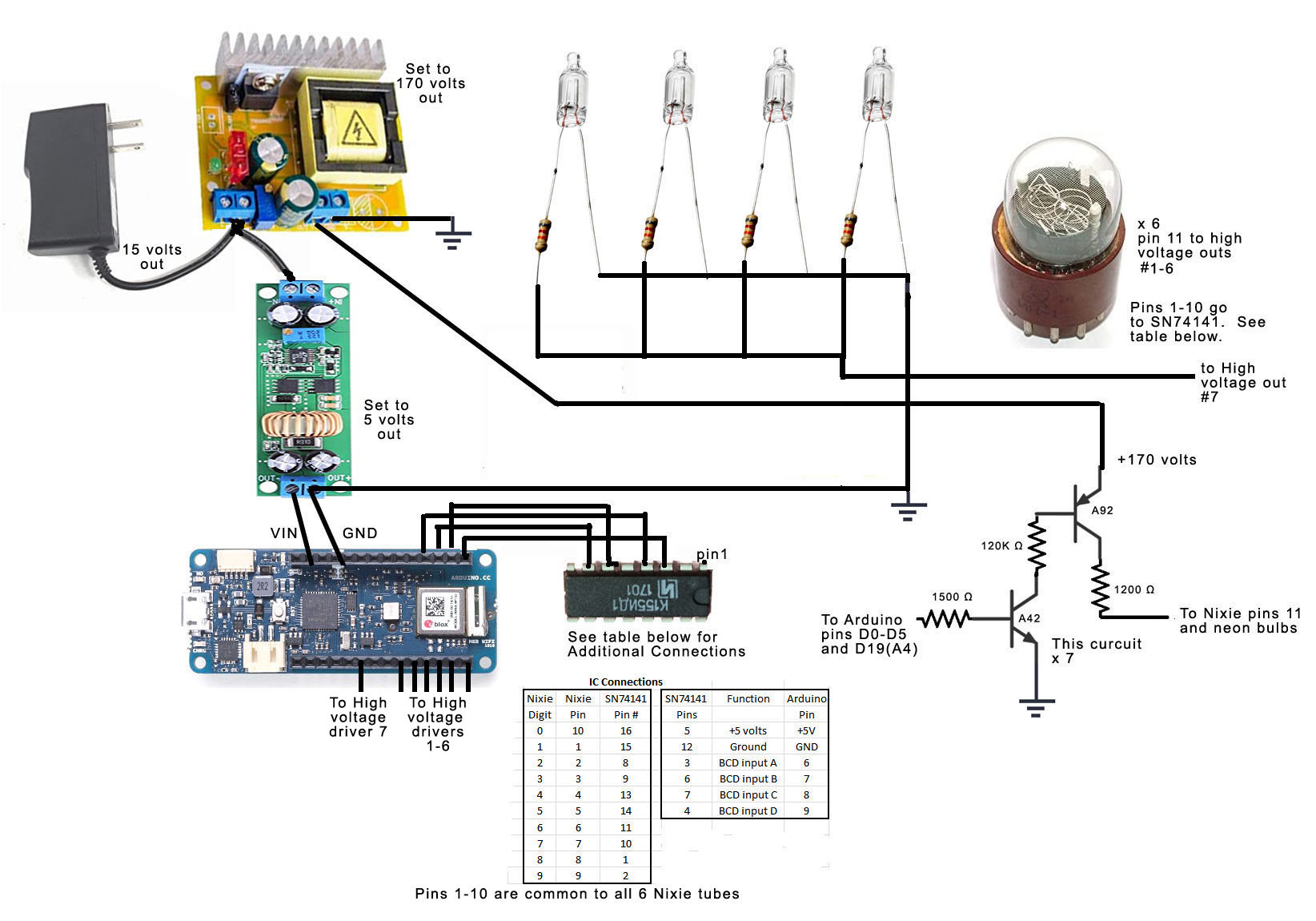
We are using the MKR WiFi 1010 for this project, because it has built-in WiFi and a built-in RTC (real-time clock). It provides a self setting clock which gets the time from the Internet. We will talk more about that in Software.
Design & ConstructionWe need to start with the obvious warning that Nixie tubes run at 170 volts, so care needs to be taken when working with these circuits, as they can give you a nasty shock!
The simplest way of powering 6 Nixie tubes would be to give them each their own BCD to Decimal cathode driver (SN74141 or the Russian equivalent K155ID1). That way the 170 volt anodes could be powered continuously and we would not need to switch the high voltage on and off. However, that involves a lot of wiring and each SN74141 would require 4 Arduino pins as inputs. We don’t have enough pins with the MKR WiFi 1010, so shift registers or something would be needed to control all the SN74141s.
To keep things relatively simple for my clock, I decided to multiplex all the Nixie tubes through a single SN74141. It simplifies the wiring, as all the Nixie tube’s cathode pins can be tied together, i.e. all 6 Nixie tube pin 1s are tied together and connected to the #1 out pin of the SN74141. The required Arduino pins are greatly reduced. We need 4 as inputs to the SN74141 and 6 to select the proper Nixie tube. (Actually, one more is needed to control the blinking colons.)
We pay for this simplicity with a few complications, however. In software, we need a timed interrupt routine to handle the constant refresh of the Nixie tubes – more on that later. In hardware, we need to be able to turn the Nixie tubes on and off by switching the high voltage on and off.
The circuit above is what I used to turn Nixies on and off. Two transistors and three resistors form a high voltage driver for each Nixie. With this arrangement, we can control the 170 volts going to the Nixie anodes directly from our Arduino. The Arduino itself never sees any high voltage, as the Arduino pin is basically tied to ground through the NPN transistor’s base-emitter junction (i.e. the base is never more than the junction's 0.7 volt forward drop above ground).
If you are familiar with Nixie tubes, you might wonder why I am using a low-value 1200 ohm resistor going to the anode of our Nixie. When the Nixie is on, its voltage drop is about 140 volts. So we have about 30 volts across that resistor and current is limited to 25 ma, which is much higher that the recommended 2 ma. But since we are multiplexing these Nixie’s and their duty cycle is only about 10%, I decided on the higher current limit to maximize brightness.
Admittedly, we need six of these high voltage drivers, so it does add some complexity, but it is still a simpler hardware arrangement than what we would need without multiplexing.
I also wanted my clock to include blinking colons between hours and minutes and between minutes and seconds. I accomplished this with the addition of 4 neon bulbs controlled through a seventh high voltage driver.
One thing I was not crazy about in this design was the need for 3 different power supplies. Of course we would need two – one for the processor and one for the 170 volt Nixie anodes. The MKR WiFi 1010 specifies a 5 volt power requirement, but the on-board regulation could have have handled a somewhat higher voltage. The DC-DC step-up supply used for the 170 volts specifies a minimum input voltage of 8 volts.
At first I planned to use a 9 volt supply as input to both the Arduino and the step-up converter, but the step-up didn’t work at 9 volts. I decided to use 15 volts, but that required a second DC-DC step-down supply to power the Arduino. So I ended up with three supplies!
Both DC-DC converters operate with a wide range of voltage outputs adjusted with the on-board potentiometer. You will need to put a meter on them and set them to the proper voltages - 5 volts for the Arduino and 170 volts for the Nixie tubes.
Before I crammed everything into the case and loaded my clock software, I decided I needed to check out the various hardware to make sure my Nixie tubes were working correctly and that I could select among the 6 Nixie tubes and neon bulbs with my high-voltage drivers. So I wrote a small test routine which I have included in the software. Below is what the test looks like:
I thought I made the 3d printed enclosure for my clock plenty big enough, but as you can see in the photo below, it got pretty crowded in there! And even though I was multiplexing the Nixies and tying most of the leads together in common, it still produced a real "rat's nest" of wires. If I was to do this clock design over again, I would have done point to point wiring between the Nixie's and mostly avoided this mess of wires.
The enclosure is 3D printed - I have included the.stl files in the available downloads. They include the face, body bottom, and body top.
SoftwareFirst, the clock software itself is the same as described in my previous tutorial: Self-Setting Super Accurate Clocks. In this tutorial, we are adding Nixie tubes as the display. The MKR WiFi 1010 has built-in WiFi and a built-in RTC (real time clock). The WiFiNina library used with the MKR 1010 has the capability of obtaining NTP (network time protocol) time. And the RTCZero library can use NTP time to set the built-in RTC. The result is a clock that sets itself and is accurate to within a few milliseconds using nothing but WiFi and the processor itself!
To use my software, you will need to obtain the WiFiNina and RTCZero libraries - they can both be installed directly from the Arduino Library Manager. You will also need to configure User Settings with your WiFi credentials, your time zone offset from GMT, and specify whether you want to clock to display 12 or 24 hour format. The software automatically acquires the time when powered up, and gets it again from the Internet once per hour, so it will stay super-accurate!
Our main loop takes the time from the RTC and corrects for the time zone and preferred time format (24 or 12 hour). It keeps the time up-to-date and ready to display in hours, minutes and seconds. It also parses the hours, minutes and seconds into the individual numbers that will be displayed on each of our 6 Nixie tubes. It turns on the colons for about ½ of each second, so that they blink once per second. The colon brightness is controlled using PWM and is simply set to roughly match the brightness of the Nixies.
A timed interrupt is called every 16 msec. to update the Nixies. It updates each Nixie by loading its respective digit into the SN74141’s BCD inputs and turning on that Nixie’s high voltage for 2.5 msec. It takes approximately 15 msec. to update all 6 Nixies, so the microcontroller is spending most of its time refreshing. Each Nixie is on for 2.5 msec. every 16 msec, so its duty cycle is 14%. They aren’t as bright as they would be if on continuously, but they are plenty bright enough for good readability. With our timed interrupt going every 16 msec, our refresh rate is 63 Hz - definitely fast enough to make us see the Nixies as on all the time!


Comments