


Hardware components | ||||||
 |
| × | 1 | |||
| × | 2 | ||||
| × | 4 | ||||
| × | 2 | ||||
| × | 2 | ||||
| × | 2 | ||||
| × | 6 | ||||
| × | 2 | ||||
| × | 1 | ||||
| × | 1 | ||||
| × | 1 | ||||
| × | 1 | ||||
Software apps and online services | ||||||
 |
| |||||
Hand tools and fabrication machines | ||||||
 |
| |||||
Pure sinewave inverters are the best inverters. They can power inductive loads and are much more efficient than simple square wave inverters. But they typically are much more complicated and more expensive than square wave inverters.
I will explain how most pure sinewave inverters work, and then show how I replaced a lot of hardware with Arduino software. Then we will build a low power demo version of this Nano based pure sinewave inverter. If you get a larger transformer and perhaps some additional power MOSFETs, this design should work for a serious high power inverter.
I am doing this for 110 volt, 60 Hz AC, but at the end of this tutorial, I will tell you how to adapt to 220 volts and 50 Hz.
Some Inverter TheoryThe simplest inverter is the square wave version. Here is how it works:
We alternately close one switch and then the other, and the transformer outputs high voltage square wave. This kind of inverter can be accomplished with a multi-vibrator running at 100 or 120 Hz and a couple of power transistors. It is very straight-forward.
Producing a sine wave, however, is much more complicated. In theory, it's pure analog, but inverters in general are switching very high currents. In order to do that switching with transistors, even big power MOSFETs, they need to be either on or off. If they spend a lot of time in transition, which analog implies, the devices overheat and burn up. So a pure sine wave can't be produced directly. Instead the devices are turned on and off 10, 000 to 50, 000 times a second. Using pulse width modulation, we digitally synthesize sine waves. Then a capacitor filters out all the high frequency leaving just a 50 or 60 cycle (low frequency) sine wave.
The synthesized sinewave is normally produced by hardware: two multi-vibrators produce square waves – one at high frequency and one at the desired output frequency, 50 or 60 Hz. Next they are both converted to triangle waves and fed into a comparator. The comparator outputs a sinewave imbedded in pulse width modulation.
Arduino Nano Replaces HardwareThis project is basically about producing that SPWM (sinewave in pulse width modulation) directly with the Nano and avoiding a lot of complicated hardware. The Nano can also replace some additional hardware we haven’t even talked about yet. Pure sinewave inverters typically include feedback circuitry to monitor the output voltage and maintain it under varying loads. They also include short circuit protection. With the addition of a few extra components, the Nano can perform these tasks as well, by reading the output voltage through an analog input pin (ADC) and then adjusting the PWM as necessary.
About TransformersThe transformer I used here is not an inverter transformer. It's a 110 to 12 volt low power step-down transformer, which worked great for experimenting with pure sinewave generation, But if you actually want to build a serious inverter, you need an inverter transformer, which efficiently operates at high current and high frequency. They are available at places like AliExpress. I never did try this with an inverter transformer - they require multiple power FETs in parallel and perhaps 50-100 amps of 12 volt input current. My little circuit board was designed to handle an amp at most, so very low power, but perfect for experimenting and testing out the concept.
Step-down transformers are designed to operated at low frequency - 50 or 60 Hz. The very small transformer I used actually worked pretty well at the 15360 Hz frequency I used for PWM, but I tried a couple of larger step-down transformers, and they hardly worked at all at 15360 Hz! So you can experiment with the small transformer that I used, or use an inverter transformer and beef up all your circuitry to handle 50- 100 amps!
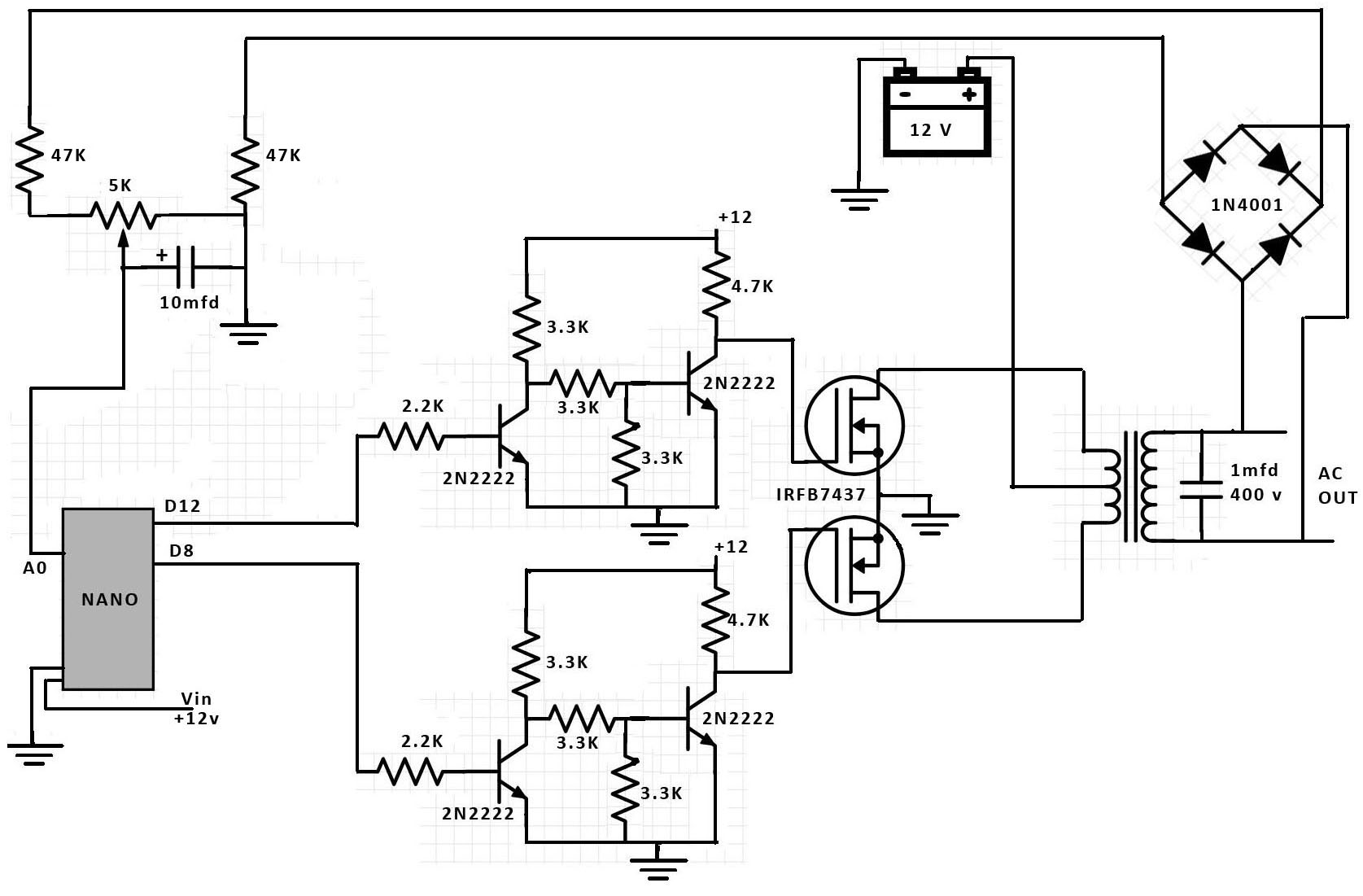
HardwareWe need two digital pins on the Nano (D8 and D12) to control two power MOSFETS, one for each half-wave of our transformer input. We are using two 2N2222 NPN transistors to drive each of the MOSFET gates. This arrangement keeps the gates grounded and the MOSFETs off unless we set the Nano digital pins HIGH, at which time the gates go to +12 volts turning the MOSFETs on and supplying power to the transformer.
There is a 1 MFD, 400 volt capacitor on the transformer’s output that filters out the high frequency PWM while leaving the power output sinewave. We also have a full-wave rectifier circuit across the output which produces a small DC output proportional to the AC output voltage. This DC output is in the range of 0-5 volts and can be read by the Nano’s A0 analog input pin and then used in software to regulate the AC voltage output.
The SPWM pulses are generated by a timed service interrupt which occurs every 65 microseconds or at 15360 Hz – that is 256 times 60 Hz. Each interrupt produces one pulse, its width modulated to form our sinewave. Our pulses can be as short as 1 microsecond, so we want to keep the interrupt service routine simple and fast. We are using direct port access instead of digitalWrite to send out our pulses. We can’t take the time to calculate any sine values, so we use a simple table of values between 0 and 63 to store our sinewave. (They were calculated in advance – actually done in an Excel Spreadsheet). We only need our table to contain one quadrant of the sinewave, as the other three quadrants can all be easily derived from the first. So our table contains 64 values between 0 and 63, and they are literally the time in microseconds that our MOSFETS are on in order to produce the required sinewave!
The other part of our software is the main loop, where we have a relatively simple proportional controller to regulate voltage. There is a lot going on in only a few lines of code. Our table of pulse widths which form a sinewave is fixed, but the timed interrupt routine is actually using a copy of the sinewave table which is being scaled in the main loop to control and maintain voltage. In each pass through the main loop, we read the feedback voltage using an analog read on pin A0. From that reading, a voltage error is calculated, representing the deviation from 110 volts. The main loop then scales the pulse width table to keep the voltage at 110 volts as the load on the output changes. The magnitude of the feedback was basically derived by trial and error, needing to be large enough to correct the voltage in a fraction of a second, but small enough to not induce oscillations into the voltage output.
You might notice in my software that the voltage error is calculated as a deviation from 2.76 volts. In theory, I would set the trim pot so that 110 volts AC produced 2.5 volts DC at A0. However, the trim pot can’t be set to exactly 2.5 volts, so I just got it close and then adjusted the software to match the feedback voltage at 110 volts.
There are a couple of other things to discuss that are going on in the main loop. First, in theory, our scaling process should always involve a multiplier less than 1. That is because our fixed pulse width table already has the peak pulse at 63 microseconds, meaning the PWM duty cycle is already peaking at 100%. But we can get more power out of our inverter by pushing the multiplier above one. We never let the pulse width exceed 63 microseconds, but we scale everything less than that up, distorting our input waveform. I was expecting this “overdrive” approach to quickly start distorting the output sinewave, perhaps only allowing a maximum multiplier of 1.1. But to my pleasant surprise, I could push the multiplier all the way to 2, while still getting a relatively undistorted sinewave at the output. And with the multiplier at 2 instead of 1, I can maintain 110 volts output with about a 50% higher output current!
One final line of code in the main loop worth mentioning sets the multiplier to 0.5 if the voltage error is very negative. If we have an excessive load or short across the output, this results in the output coming way down, protecting the transformer and MOSFETs from overheating. If the load is reduced, the voltage rises enough to reset and normal operation is restored.
Sinewave ResultsAbove is the waveform with no load. The output is 110 volts at 0 amps. You can see a little noise on the waveform and a slight distortion of the sinewave itself, but not bad.
This is the waveform with about a 10 watt output. The output is 110 volts at 0.09 amps. The waveform is a near perfect sinewave, but with a little noise on it.
ConclusionsUsing the Arduino Nano to generate the SPWM for a pure sinewave inverter works great. I was able to easily experiment with different frequencies and various feedback and control options.
220 Volts @ 50 HzThe changes you will need to use this circuit for 220 are very straight forward:
1. You will need use a 220 volt inverter transformer instead of 110 volts.
2. You will need to set up the interrupt timer for 256 * 50 Hz instead of 256* 60 Hz. To do that, change the timer in Setup to the code below.
3. You probably should change the 2MFD capacitor from a 400 volt rating to 600 volts.
4. You might want to change the trim pot from 5K ohms to 2K ohms.
// TIMER 1 for interrupt frequency 12800 Hz - 50 Hz * 256cli(); // stop interruptsTCCR1A = 0; // set entire TCCR1A register to 0TCCR1B = 0; // same for TCCR1BTCNT1 = 0; // initialize counter value to 0// set compare match register for 12800 Hz incrementsOCR1A = 1249; // = 16000000 / (1 * 12800) - 1 (must be <65536)// turn on CTC modeTCCR1B |= (1 << WGM12);// Set CS12, CS11 and CS10 bits for 1 prescalerTCCR1B |= (0 << CS12) | (0 << CS11) | (1 << CS10);// enable timer compare interruptTIMSK1 |= (1 << OCIE1A);sei(); // allow interrupts


Comments