


Hardware components | ||||||
 |
| × | 1 | |||
| × | 1 | ||||
| × | 1 | ||||
 |
| × | 1 | |||
| × | 1 | ||||
Software apps and online services | ||||||
| ||||||
| ||||||
| ||||||
| ||||||
| ||||||
Hand tools and fabrication machines | ||||||
 |
| |||||
| ||||||
| ||||||
I needed an WS2812 LED controller, and went with an ESP8266 based solution. My ceiling fans have SOnOff relays running tasmota. The ESP8266 allows for WiFi connectivity, and supports these LED strips.
Install PrerequisitesDownload and install Python.
If compiling source, download and install git.
Get tasmota binaryIf you prefer to compile from source yourself, skip to the next section. If you prefer to simply download the precompiled binary, get it from here: https://github.com/arendst/Sonoff-Tasmota/releases/download/v6.3.0/sonoff.bin
Download and compile sourceIf you downloaded the sonoff.bin file, then skip this section.
Open a git bash window.
From the prompt, download the tasmota source code:
git clone https://github.com/arendst/Sonoff-Tasmota.git
Create, activate, and install a platformio virtual environment:
virtualenv platformio
platformio\Scripts\activate
pip install platformio
To be continued...
Flash FirmwareConnect USB-TTL serial adapter to test leads and clip on to TX, RX (transmit goes to receive, receive goes to transmit; if you get them backwards, just swap them). Connect the ground from the USB adapter, GND on the Wemos/Lolin D1 mini (ESP8266), and GPIO0/D3 to the same row on a solderless breadboard.
Open a command prompt
virtualenv esptool
esptool\Scripts\activate
pip install esptool
Power on the Wemos/Lolin D1 mini by plugging in a micro-USB cable.
Change directories to where you downloaded sonoff.bin, and run:
cd Downloads
esptool write_flash 0x0 sonoff.bin
There are more complete instructions at: https://github.com/arendst/Sonoff-Tasmota/wiki
Configure SettingsRemove the lead from GPIO0/D3, and press the reset button.
Run Putty, and connect to the COM port assigned to the USB-TTL serial adapter; use a baud rate of 115200. Alternately, it may be easier to log in to your WiFi hotspot to get the IP address assigned to the microcontroller.
Connect to a WiFi hotspot with a name of sonoff-XXXX. It should allow you to configure up to two SSID's and passwords. Once configured it will reset.
Pay attention to the IP address assigned.
With a web browser, connect to http://ip-address (typically a 192.168.x.y)
- Select Configuration
- Select Configure Module
- Drop down Module type, and select 18 Generic
- Save, which will cause it to reboot. Wait a few seconds and page should refresh back to main menu.
- Select Configuration
- Select Configure Module
- Drop down D1 / GPIO5, and select 07 WS2812.
- Save, which will reboot again.
- Once page refreshes, select Toggle.
- Move slider bar to middle.
Feel free to poke around in the rest of the configuration. If you're not using an MQTT broker, like mosquito, you should disable it. If you have an Amazon Echo (Alexa), you can enable Philips Hue emulation.
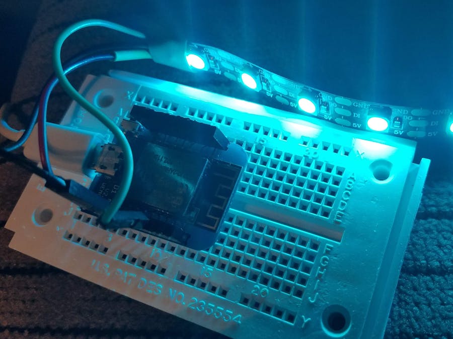
Solder ConnectorDecide whether you want your connector coming up away from the board, or down. You should tin the ends of the JST connector, with some solder. However, too much will not allow you to insert it into the through hole. Connect the red connector to 5V, white to GND, and green to 5 (GPIO5 / D1). Image is before I trimmed the excess length of wire, as to prevent them from shorting out.
Connect JST connectors, then the USB. LEDs should illuminate.
The ESP8266 runs at 3.3VDC, and the LED Strip runs at 5VDC. You may need to add a transistor level up shifter.

Comments