Building a Basic User Interface with RT-Spark's Built-in LCDFor this lab, I explored the RT-Spark (Spark-1) development board's built-in 240x240 LCD, paired with 5 momentary switches and 3 LEDs to create a simple, interactive user interface.
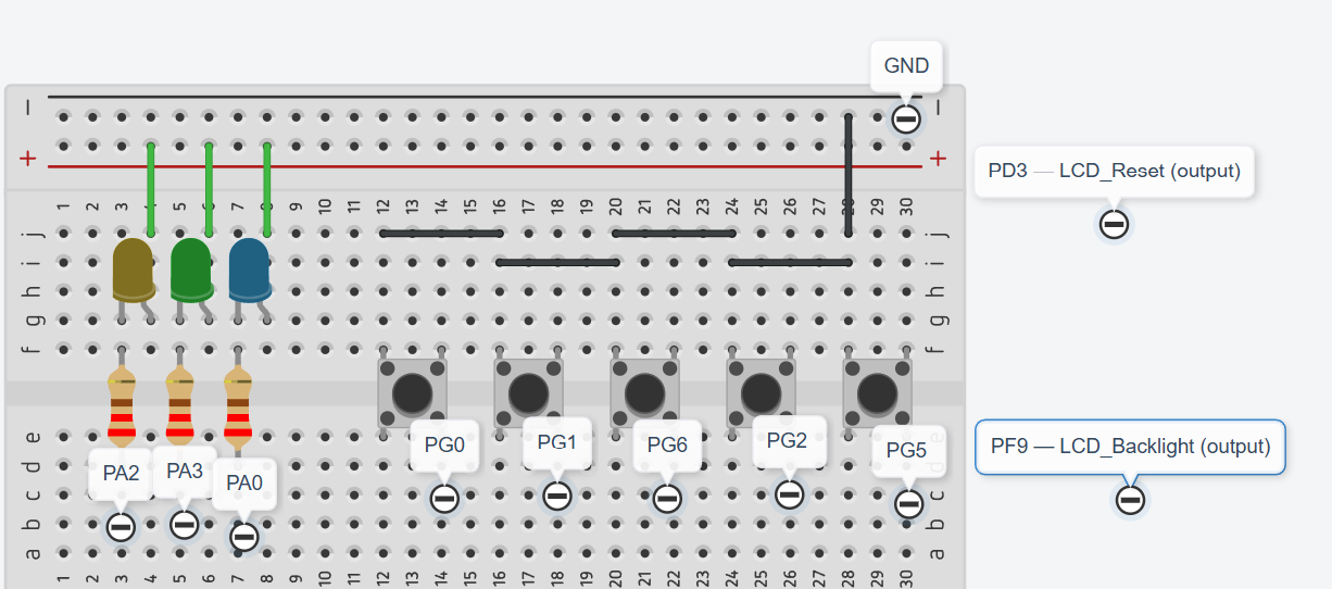
The build started with getting the onboard LCD working through the FSMC peripheral, using a bare-metal driver (drv_lcd) to handle backlight, reset, and display initialization. Once "Hello World" showed up on screen, the next step was wiring in the Up, Down, Left, Right, and Center switches on GPIOG, using the MCU's internal pull-ups so no external resistors were needed.
The LEDs (Red, Green, Blue) on GPIOA were tied to the Up, Center, and Down switches respectively, so pressing a button both lights its corresponding LED and updates the LCD with which button is currently pressed.
One interesting debugging detour: the LEDs initially refused to light up no matter what GPIO mode I tried (open-drain, then push-pull). After checking the registers and confirming the pins were toggling correctly, the issue turned out to be LED polarity — the wiring orientation didn't match the active-low logic in the code. Swapping the LED polarity fixed it instantly, turning this into a good reminder that "working code, dead hardware behavior" usually means it's time to check the physical wiring, not the registers.
The final result: a responsive five-button interface where each press is reflected instantly on both the LCD text and the corresponding LED.






Comments