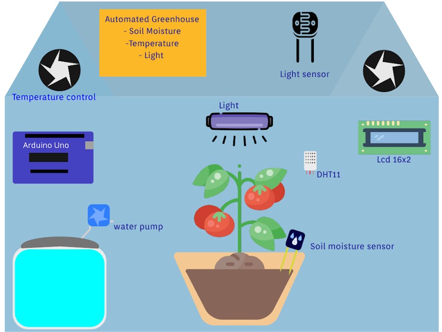
there are many variables in the greenhouse environment, to control this variables we use sensors to acquire data about them then act using the relay module.
This prototype works as next :
inputs: - DHT11 (Humidity and Temperature)
- Soil moisture sensor (soil moisture)
- LDR (light detector)
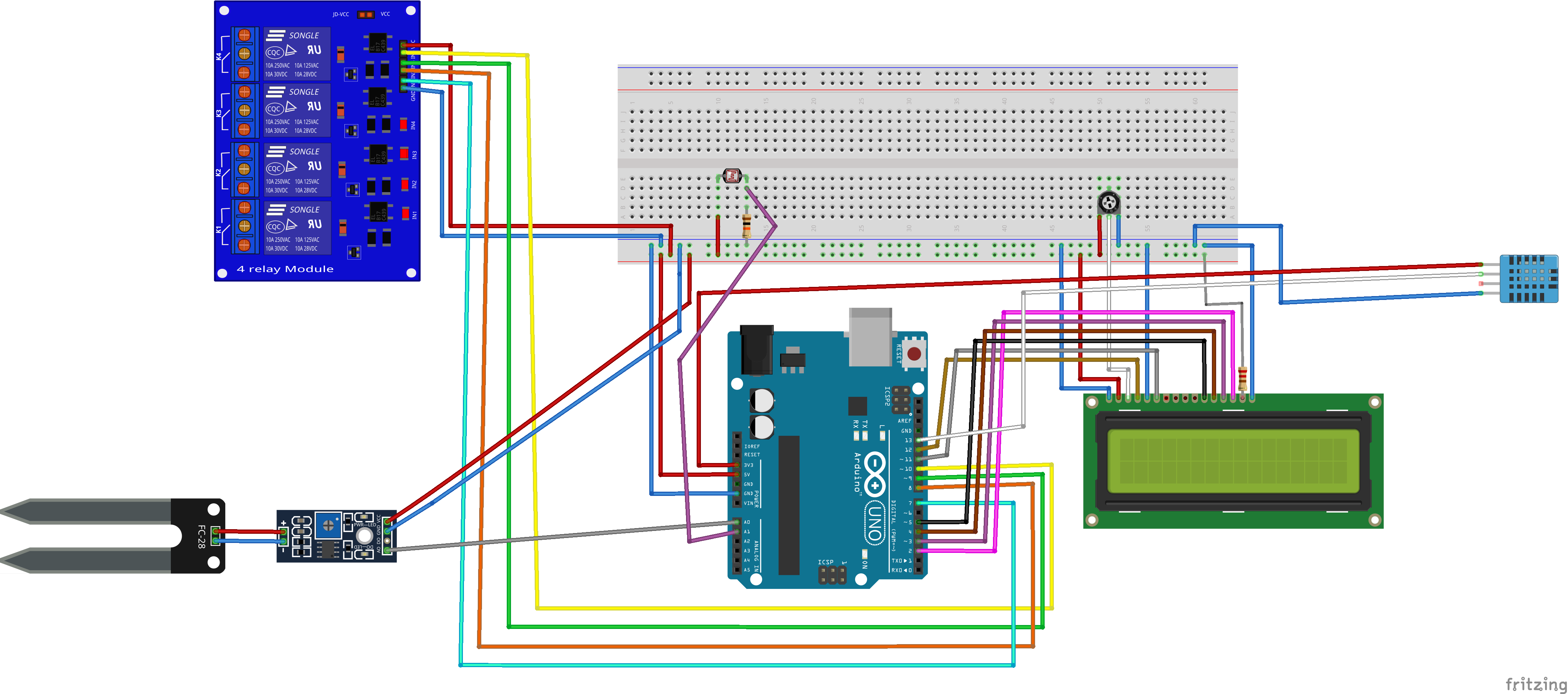
outputs : - 4-relay module
conditions used :
- when soil moisture gets under 60% the water pump activates by relay-1
- when temperature gets under 20 C° the heating system gets activated by relay-2
- when the temperature gets above 30 C° the cooling system activates by relay-3
- when outside greenhouse light fade the light gets on by relay-4
the above thresholds can be changed in code according to your crop conditions

_ztBMuBhMHo.jpg?auto=compress%2Cformat&w=48&h=48&fit=fill&bg=ffffff)


_3u05Tpwasz.png?auto=compress%2Cformat&w=40&h=40&fit=fillmax&bg=fff&dpr=2)


Comments