


Hardware components | ||||||
| × | 2 | ||||
| × | 2 | ||||
| × | 1 | ||||
 |
| × | 1 | |||
| × | 1 | ||||
| × | 4 | ||||
 |
| × | 2 | |||
| × | 4 | ||||
| × | 4 | ||||
| × | 2 | ||||
Stepper motors are in 3D printers, CNC machines, camera sliders and half the projects on this site. We tell them "go 360 degrees" and trust that they did.
But how accurately does a stepper return to the same spot if you actually measure the shaft instead of trusting the step count?
To find out, I built a small mechanism: two discs, each with a thin gap, mounted at 90 degrees to each other so one can spin through the other's gap. Motor A turns one revolution and stops with its gap lined up, then Motor B does the same, and they repeat. If either stops too far off, the discs collide. That makes the errors easy to see, not just read off a screen.
Get the full video on https://drive.google.com/file/d/1BkCM5rY54M2rqCIt7W2QsBgWdYdd8Yan/view?usp=sharing
This is the full build log, written so you can copy it: parts, printing, wiring, code, and what I measured.
Step 1: Print the frame and the discsI printed the frames first, and then the two discs.
The lower disc is printed slightly smaller than the upper one, so it doesn't scrape the bottom of the frame as it turns. That's the one dimension worth checking before you print.
All the measurements of the discs and frame is given in CAD.
Step 2: Attach the magnet to the encoder side of each motorThe encoder reads the angle from a magnet on the back of the motor shaft. Stick a diametric magnet to the centre of the rear shaft, facing the MT6701 chip on the board.
Keep it centered over the sensor about 1 to 2 mm away from the chip, firmly attached
For each motor:
- Fix the Stepper board to the back of the NEMA 17 with screws and spacers.
- Place the motor on the frame.
- Mount the disc on the front shaft.
Repeat for the second motor, which sits higher and at 90 degrees to the first so the discs overlap in the same space.
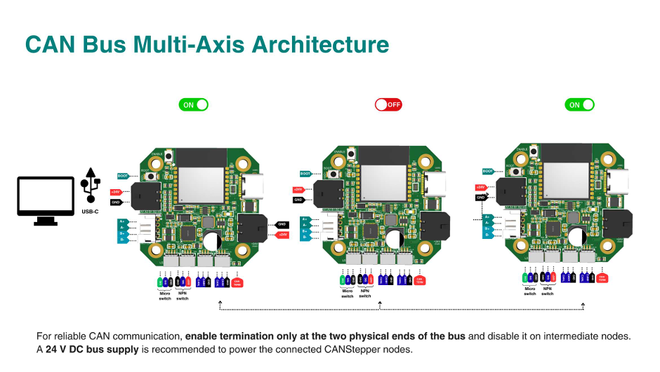
CAN: connect CAN OUT of the upper motor's board to CAN IN of the lower motor's board.(schematics are uploaded)
Other wiring: JST PH 2.0 mm (4 pin positions), JST PH 1mm (3 pin position)
Power: both boards run from the 24 V supply through the Micro-Fit 3.0 connectors.
USB: connect one board to your computer with USB-C.
Step 5: Flash, give each board an ID, and talk to themEach board needs its firmware flashed and a unique node ID (I used 2 and 3). The quickstart covers that: https://docs.grafito.in/docs/quickstart
Step 6: Teach it "home"I don't assume the power-on position is zero. I turn both discs by hand until each gap is correctly aligned, then record each motor's raw encoder reading. Those become the reference positions.
Because the encoder angle wraps every revolution, the software works out the shortest distance back to the reference after each move.
Step 7: Run the sequence, then add PID and a lookup tableThe loop is:
- Check the other motor is correctly aligned.
- Turn this motor one revolution.
- Read the encoder and correct if needed.
- Confirm it's safe, then hand over to the other motor.
The second motor never moves just because the first one finished sending steps. The encoder has to agree first.
PID: the board compares planned and measured position and corrects the difference. My two motors didn't want identical settings, so I tuned each one.
Lookup table (LUT): even after PID, one motor stopped slightly past the target by about the same amount every time. Since it was repeatable, I measured it and shifted the command the other way. PID controls the motion, the LUT cancels the predictable endpoint error, and the encoder checks what really happened.
What I measuredWith identical PID settings, a single side-by-side test without LUT gave the stopping error of about 0.286°and with LUT the error around 0.022° (one encoder count). That is about 13 times smaller.
What I learned- Step commands aren't the same as physical position. The encoder tells what the shaft really did.
- Encoder resolution only helps if the magnet, shaft and mounting are solid.
- A repeatable error is useful information, because I could measure it and correct it.
- CAN keeps multi-motor wiring tidy: one bus, separate addresses.
Three or more motors, automatic LUT calibration, load-dependent compensation, real-time error plots, and maybe turning the discs into a little kinetic sculpture.


Comments