

Hardware components | ||||||
| × | 1 | ||||
| × | 1 | ||||
 |
| × | 1 | |||
Software apps and online services | ||||||
| ||||||
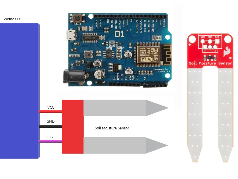
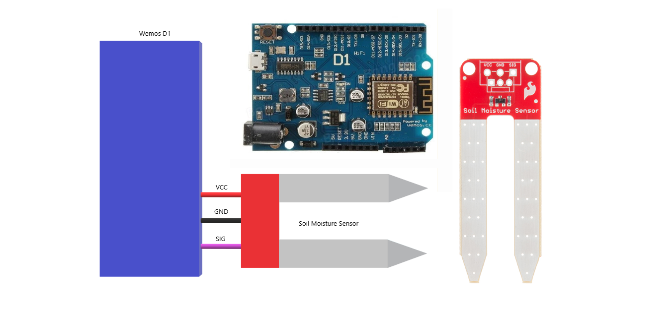
We can use wemos d1 and soil moisture sensor.
Youtube vidoe : https://youtu.be/7C0ENAmEkOg
1. Soil Moisture Sensor :
Hardware Overview and Assembly :
The Soil Moisture Sensor is pretty straightforward when it comes to hookup. There are only three pins to connect: VCC, GND, and SIG.
You need to supply power to VCC and GND. We recommend not powering the sensor constantly to prevent corrosion of the probes (more on this in a bit). SIG provides an anlog signal out that can be attached to the ADC pin on any microcontroller. The value read on SIG will vary depending on the voltage with which you power the sensor.
Theory of Operation :The two probes are acting as a variable resistor – more water in the soil means better conductivity and results in a lower resistance and a higher SIG out. Your analog readings will vary depending on what voltage you use for Vcc as well as the resolution of your ADC pins.
Powering the Soil Moisture Sensor :We recommend powering the Soil Moisture Sensor with between 3.3V - 5V. Please note that the analog value returned will vary depending on what voltage is provided for the sensor.
One commonly known issue with soil moisture senors is their short lifespan when exposed to a moist environment. To combat this, we’ve had the PCB coated in Gold Finishing (Electroless Nickel Immersion Gold).
Another way to extend the lifespan of your sensor is to only power it when you take a reading. Using a digital pin set to HIGH on an Arduino, for example, is an easy way to accomplish this. If you wish to power the sensor with more than a digital pin on your microcontroller can provide, you could always use a transistor.
AssemblyIf you bought the Soil Moisture Sensor that already has the 3-pin screw terminal attached, you may skip this section.
As for connecting the senor to your circuit, we’ve given you a few different options. You can solder on a 3-pin JST Jumper Wire Assembly if you need to easily switch sensors on your project. This pairs nicely with our JST to Breadboard Jumper connector.
Another option is to solder on a 3-pin 3.5mm Screw Pin Terminal for a slightly more robust connection.
2. Wemos D1 :
- 11 digital input/output pins, all pins have interrupt/pwm/I2C/one-wire supported(except for D0)
- 1 analog input(3.2V max input)
- Micro USB connection
- Power jack, 9-24V power input.
- Compatible with Arduino
- Compatible with nodemcu
Microcontroller --> ESP-8266EX
Operating Voltage --> 3.3V
Digital I/O Pins --> 11
Analog Input Pins --> 1(Max input: 3.2V)
Clock Speed --> 80MHz/160MHz
Flash --> 4M bytes
Length --> 68.6mm
Width --> 53.4mm
Weight --> 25g
Pin :Pin | Function | ESP-8266
TX | TXD | TXD
RX | RXD | RXD
A0 | Analog input, max 3.3V input | A0
D0 | IO | GPIO16
D1 | IO, SCL | GPIO5
D2 | IO, SDA | GPIO4
D3 | IO, 10k Pull-up | GPIO0
D4 | IO, 10k Pull-up, BUILTIN_LED | GPIO2
D5 | IO, SCK | GPIO14
D6 | IO, MISO | GPIO12
D7 | IO, MOSI | GPIO13
D8 | IO, 10k Pull-down, SS | GPIO15
G | Ground | GND
5V | 5V | -
3V3 | 3.3V | 3.3V
RST | Reset | RST


Comments