

Hardware components | ||||||
| × | 1 | ||||
 |
| × | 1 | |||
 |
| × | 1 | |||
 |
| × | 1 | |||
Software apps and online services | ||||||
| ||||||
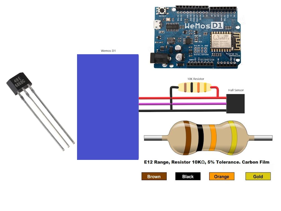
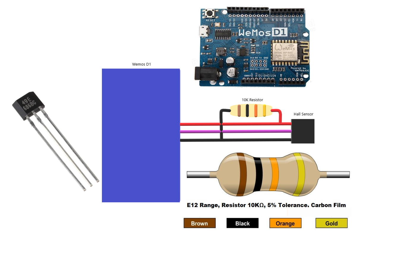
Sensors have always been a vital component in any Project. These are the ones which convert the real real-time environmental data into digital/variable data so that it can be processed by electronics. There are many different types of sensors available in the market and you can select one based on your requirements. In this project we will learn how to use a Hall sensor a.k.a Hall effect sensor with Arduino. This sensor is capable of detecting a magnet and also the pole of the magnet.
Why detect a magnet?, You may ask. Well there are a lot of applications which practically use Hall Effect sensor and we might have never noticed them. One common application of this sensor is to measure speed in bicycles or any rotating machines. This sensor is also used in BLDC motors to sense the position of Rotor Magnets and trigger the Stator coils accordingly. The applications are endless, so let’s learn how to Interface Hall effect sensor Arduino to add up another tool in our arsenal. Here are some projects with Hall sensor
In this tutorial we will use interrupts function of Arduino to detect the magnet near Hall sensor and glow a LED. Most of the time Hall sensor will be used only with Interrupts because of their applications in which high reading and executing speed is required, hence let us also use interrupts in our tutorial.
1. Hall Effect SensorsBefore we dive into the connections there are few important things that you should know about Hall Effect sensors. There are actually, two different types of Hall sensors oneis Digital Hall sensor and the other is Analog Hall sensor. The digital Hall sensor can only detect if a magnet is present or not (0 or 1) but an analog hall sensor’s output varies based on the magnetic field around the magnet that is it can detect how strong or how far the magnet is. In this project will aim only at the digital Hall sensors for they are the most commonly used ones.
As the name suggests the Hall Effect sensor works with the principle of “Hall effect." According to this law “when a conductor or semiconductor with current flowing in one direction was introduced perpendicular to a magnetic field a voltage could be measured at right angles to the current path." Using this technique, the hall sensor will be able to detect the presence of magnet around it. Enough of theory, let’s get into hardware.
- 11 digital input/output pins, all pins have interrupt/pwm/I2C/one-wire supported(except for D0)
- 1 analog input(3.2V max input)
- Micro USB connection
- Power jack, 9-24V power input.
- Compatible with Arduino
- Compatible with nodemcu
Microcontroller --> ESP-8266EX
Operating Voltage --> 3.3V
Digital I/O Pins --> 11
Analog Input Pins --> 1(Max input: 3.2V)
Clock Speed --> 80MHz/160MHz
Flash --> 4M bytes
Length --> 68.6mm
Width --> 53.4mm
Weight --> 25g
PinsPin | Function | ESP-8266
TX | TXD | TXD
RX | RXD | RXD
A0 | Analog input, max 3.3V input | A0
D0 | IO | GPIO16
D1 | IO, SCL | GPIO5
D2 | IO, SDA | GPIO4
D3 | IO, 10k Pull-up | GPIO0
D4 | IO, 10k Pull-up, BUILTIN_LED | GPIO2
D5 | IO, SCK | GPIO14
D6 | IO, MISO | GPIO12
D7 | IO, MOSI | GPIO13
D8 | IO, 10k Pull-down, SS | GPIO15
G | Ground | GND
5V | 5V | -
3V3 | 3.3V | 3.3V
RST | Reset | RST


Comments