

Introduction:
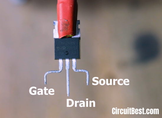
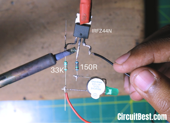
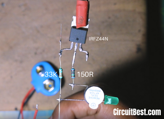
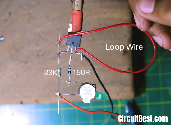
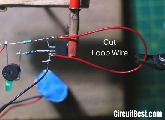
The Wire Break alarm is reasonably associate withEmergency Alarm Circuit. it's a loop sensing element in it. The loop may be a straightforward piece of Copper Wire for shorting 2 terminals. The circuit wants 9-12V for General Operation. In general, if we tend to cut this wire then the circuit became open-circuited. There are several wire break alarm circuit applications.The first time once the wire loop is connected than the present flows from the Vcc to GND through a 33k electrical device. currently, once you cut the loop wire then the present flows from the Vcc to MOSFET’s Gate pin. So, it activates the MOSFET. As a result, the MOSFET became conductive. As a result, current flows from Drain to supply. So, the Load that is connected with the MOSFET is steam-powered up. you'll conjointly use this Circuit as a broken wire detector project report.
How will the Wire Break Alarm circuit work?
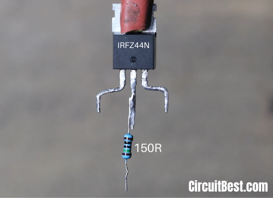
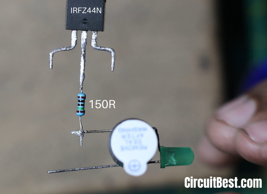
This is an awfully simple circuit supported by a MOSFET semiconductor unit. Whenever we have a tendency to offer power to the circuit then this flows from 33k electrical device than from the wire loop then goes to the GND. Now after you cut the loop wire then this flows from the Vcc to MOSFET’s Gate pin. So, it activates the MOSFET. As a result, the MOSFET became semiconducting. As a result, current flows from Drain to supply. So, the Load that is connected with the MOSFET is going to be high-powered up. Here you want to connect a current limiting resistance. For the LEDs and also the Buzzer. Otherwise, the light-emitting diode might fuse.so these area unit wire break alarm circuit applications.
Conclusion:
All in all, we will say that there's such a lot of Application of wire break alarm circuit. you'll build a Home safety protection circuit with this cut wire alarm circuit. The elements square measure thus low cost and may be found from Utsource and additionally in native outlets. an equivalent sort of security protection will be organized with Microcontrollers like Arduino, Raspberry Pi, PIC ICs, and lots of different controllers. however, those don't seem to be low cost. So, this is often an easy wire break alarm circuit with negligible elements.
- Please Subscribe to My Youtube Channel.
- Visit My Website: CircuitBest.com
- Sponsor Link: UTSOURCE
Step 1

Step2

Step 3
Step 4
Step 6

Step 7
Step 8


Comments