
Introduction:
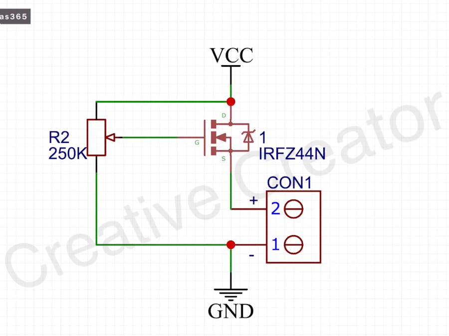
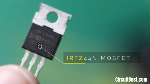
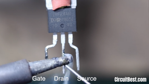
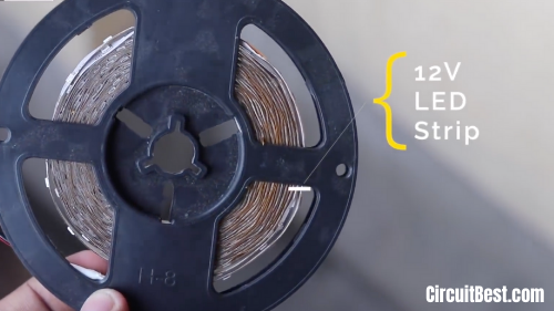
Today during this article we are getting to discuss the dc LED dimmer with IRFZ44N MOSFET. We are using very minimal components within the Circuit Diagram. Just an IRFZ44N N-Channel Mosfet and a Potentiometer. The IRFZ44N is an N-Channel Enhancement type MOSFET thereto can Deliver high Output for an easily led dimmer. This Circuit also works with other N-Channel Mosfets also. that's just about it and you'll use the Circuit for LED Dimming. I will be able to thank Utsource for sponsoring.
Watch Video for led bulb dimmer circuit:
Watch the YouTube video from the Creative Creator for more detailed instructions. you'll see step by step process for creating the dc dimmer.
How does the 12v Strip Dimmer Circuit Works?
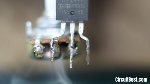
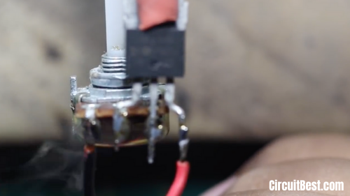
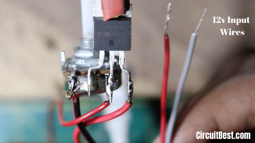
- This is an easily led dimmer that has only 2 components. One is an N-Channel Mosfet and a Potentiometer. The Potentiometer is connected with the MOSFET's GATE Pin.
- Now rotate the potentiometer. this may adjust the Gate Voltage. For the Gate Voltage, The Drain to the source voltage will change.
- As a result, the voltage will vary consistent with the Potentiometer Rotation.
- In this way, the led dimmer circuit with a potentiometer will work.
NOTE:
- Please Subscribe to My Youtube Channel.
- Visit My Website: CircuitBest.com
- Sponsor Link: Utsource
Conclusion:
All in all, we will say that there's numerous Application of LED Strip Dimmer. you'll make 100W Dimmer circuit, Motor Speed Controller with this board. The components are so cheap and may be found from Utsource and also in local shops. an equivalent sort of security protection is often arranged with Microcontrollers like Arduino, Raspberry Pi, PIC ICs, and lots of other controllers. But they aren't cheap. So, this is often an easily led dimmer with minimal components. You can also read another article about Wire Break Alarm Circuit.
Step 1

Step 2
Step 3
Step 4
Step 5
Step 7
Step 8


Comments