
Today in this article we are going to discuss How to Make a High Power amplifier circuit with 13007 Transistor.
You can find all the components from old damaged Power supplies. So you can also recycle old Electronics.
Also, I have given buying links here.
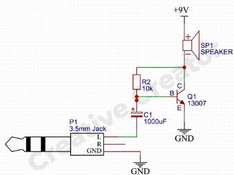
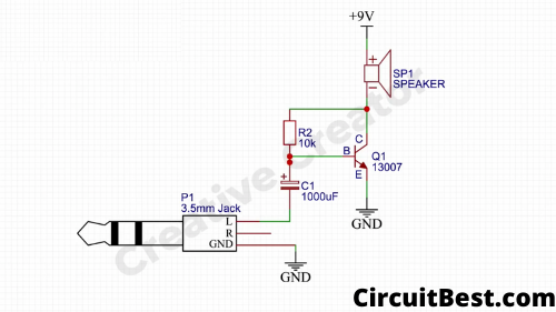
How does the 13007 Amplifier Circuit work?This is an Easy circuit base on an NPN Transistor. The Transistor's Base takes the low audio signal and then amplifies the signal. To a Higher amplitude. Higher amplitude means High Volume.
Now If you connect a Speaker 🔊 load then it will run it.
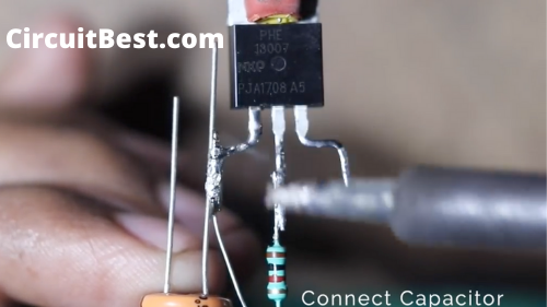
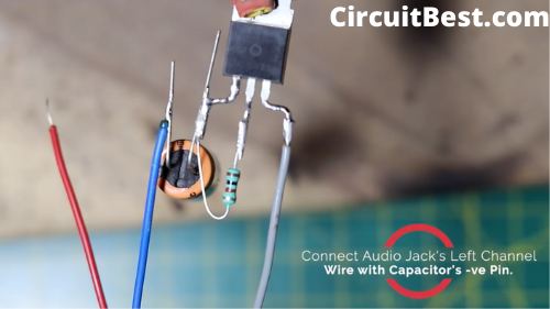
Here I have used a 1000uf Capacitor for absorbing the Higher Frequencies. Now the transistor will give a great result.
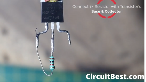
Here I used 1k Resistor for removing lower Frequencies. This will increase the sound quality of the speaker.
When the Base of the transistors gets to the low amplitude signal then the base became active in this state. For this reason, the Transistor became a conductive Collector to Emitter. In this way, the Speaker Runs.
Watch Youtube Video:Conclusion:So, this is a Simple amplifier circuit made up of 13007 Transistors. The audio quality is really loud from the amplifier. It is just a 3 component amplifier.
Great for personal usage.
If you have some old power Supply then you can get all the components easily there. The construction is pretty much simple. Anyone ca
All components are available at the UTSOURCE official store. You can get some good deals from there store. Sometimes they offer you express shipping for free which is really great in my opinion.
Step 1
Step 3
Step 4
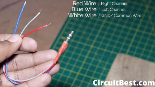
There are 3 wires in the 3.5MM jack. One is White/ Gray and the other two are Red and Blue. The white/ gray wire is the common GND wire. Not the Red and The white wire is for the Stereo Left and Right Channel Output.
This is a test Circuit. Here I have used a 1 channel circuit. For testing, I have used one Common wire i.e. White wire, and anyone of the channel wire. From the Red and the Blue Channel wire, I am using the Blue channel wire. This is like a personal Preference. You can also use other wire as well. Both will work great.
Step 5
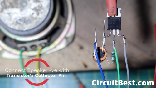
Connect the speaker -ve with the 13007 Transistor's collector pin. For the Speaker +ve, we have to connect it in the next step.
Step 6
If you want good current output from the power supply then I have Included links for some good power supplies.
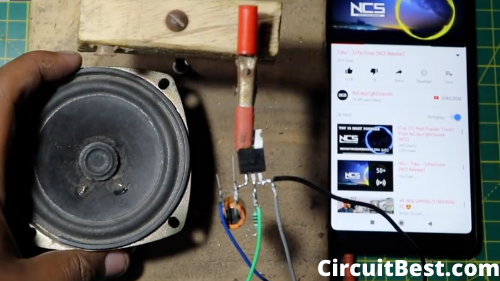
By the way, let's connect 12v Power with the circuit. The -ve or the GND wir2 form the power supply will be connected with the 13007 Transistor's Emitter pin. Now, the +ve wire from the power supply will be connected with the Speaker +ve.
Step 7
Keeping the lowest Components possible you can see the sound from the amplifier is absolutely Insane. There are some minimal components used in the circuit.


Comments