
Today right now will Discuss the Relay module. Here I will make a 12 Channel transfer Board. This hand-off board interfaces through Bluetooth. What's more, in particular, you can control room lights/all heaps with a solitary pinch of your Phone. along these lines, likely numerous clients will like it on the off chance that they don't have any substantial IR sensor in the Phone. The Brain of this Project is Arduino. Along these lines, fundamentally, you will figure out how to compose a straightforward Arduino code.
For the components section, I have gone with UTSOURCE. They are one of the largest component suppliers in China. They offer different types of components such as Resistors, Capacitors, ICs and many other things. You will get exclusive discounts If you order from them. So, why you are waiting for? Place your first order from UTSOURCE.
0 Profit selling KN95 masks and Infrared Thermometer from UTSOURCE.net: https://www.utsource.net/home/healthcare
Watch YouTube Video:Here is the video about the 12 Channel Bluetooth Controlled Relay Module with Arduino Nano. Watch the video till the End you will get Everything. It is anything but difficult to control the room lights.
Circuit Schematics:I have made the circuit outline on Online free Software EasyEDA. I have likewise utilized a few hubs for making the associations straightforward.
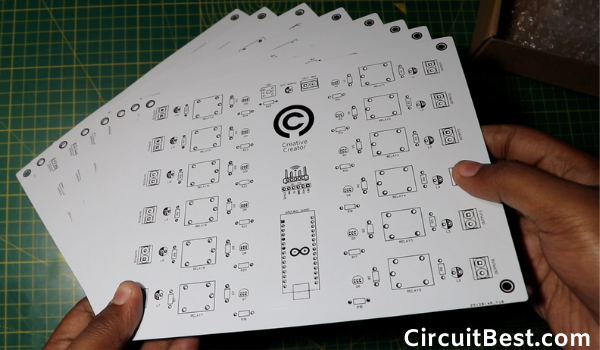
There are numerous parts in the circuit. Keeping everything in my psyche I have additionally made an appropriate PCB for the circuit. I requested it from JLCPCB. Here is the PCB Front Layout.
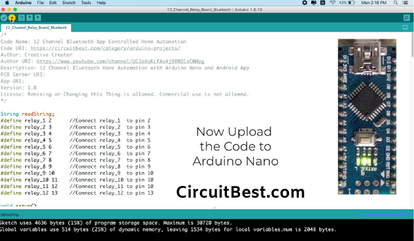
The fundamental heart of this venture is Arduino Nano. What's more, for the remote correspondence, I am utilizing an HC05 Bluetooth Module. What's more, for dealing with the High loads I am utilizing 12 Relays couple with some driving transistors.
And ultimately, for controlling the circuit we will require an application. BTW I have planned an application from MITApp Inventer for this venture.
Blocks:Here are largely the individual squares for making the application. On the off chance that you are structuring the application for yourself, at that point, this may support you. Here I utilized Toggle Button So the Code is somewhat long I think as I would see it. You can likewise utilize some straightforward press fastens in the application. The Pushbuttons will limit the Code. Yet, For my situation, I find that the Toggle Buttons look progressively noticeable from Pushbuttons.
At next Let's Talk about the circuit. I mean How the 12 Channel transfer module functions? The Arduino has advanced pins just as simple pins. Here I have utilized every computerized pin which are I think altogether is 12. I utilized every one of them.
The Digital pins give High or Low Pulses. High methods 1 and Low methods 0. The High heartbeats turn the Driver Transistor on and afterward the Driver Transistor turns the transfers on for loads.
How does the Wireless Connectivity work to Control Your Room Lights With Your Phone?The remote association is done through HC05 Bluetooth Module. At the point when you divert the Switch on from the telephone then the application sends a Massage to the Arduino through HC05. At that point, we have included two or three 'It-Else' conditions. Presently for a solitary back rub, A solitary line will be executed. On the off chance that this doesn't fulfill the condition, at that point it will naturally change to straightaway 'If-Else' condition. Right now, condition fulfills and the transfers will be on for loads.
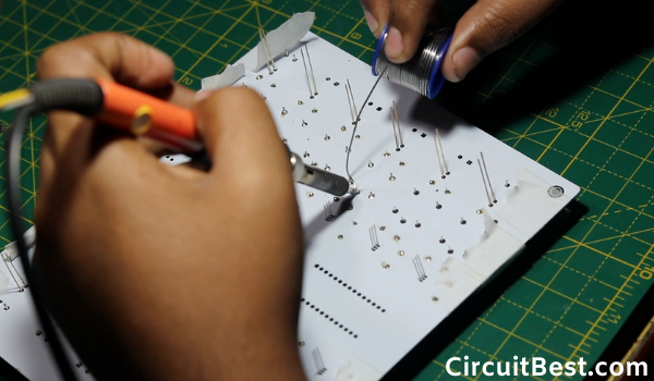
Note:I have utilized Sticky Tape for fixing all the segments in its place. Thus, the parts won't move from its place. After the Soldering procedure finishes, we can evacuate the Sticky Tape.
In the wake of expelling all the Sticky Tabe, the PCB looks extraordinary. Here is the closeup of the PCB. The welding process is simple due to Prebound copper follows.
At present, My application is just accessible for Android clients. On the off chance that I plan the application for iOS, at that point I will refresh this later.
For the time being open Bluetooth in your Android Device. At that point search for HC05 Bluetooth. The default secret key for the Bluetooth is 1234 or 0000. More often than not, the secret word is 1234.
Presently give the secret phrase and associate it with your Bluetooth.
Download Links:- Schematics: Download
- PCB Image: Download
- Home Automation PCB Garber: Download
- App Inventor Block Image: Download
- Arduino Bluetooth Home Automation Code: Download
- Home Automation App: Download
Along these lines, all things considered, I can say it is an enjoyable venture, in any case. Be that as it may, I confronted a few troubles while making the undertaking. For example, making the application. I am not an application engineer from my experience. In this way, it took a great deal of time. Be that as it may, finally, I thought of a completely working 12 channel hand-off module circuit with Bluetooth. I will express gratitude toward JLCPCB for making this video conceivable. Something else, there are such a large number of associations. Appending this circuit in a breadboard resembles genuine annoyance. So we can pronounce the task an extraordinary achievement. All schematics, PCB structure, PCB creation record, Arduino Code, application Inventor hinders all are given in the portrayal. I trust you folks like my interpretation of the 12 channel transfer module Board with Arduino Nano.
You can likewise peruse our different articles about Arduino.
Step 1

Step 2
Step 3
Step 4
Step 5
Step 6
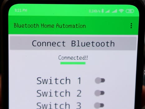
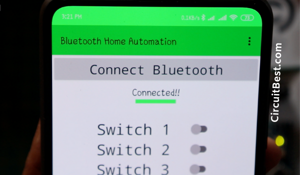
Presently open the application and snap on the Connect Button. Presently from the given menus select the HC05 Bluetooth.
Just because when you have not associated with the Bluetooth then the Bar shading will be Red. After you associate the Bar will be Green.
Right now, we can distinguish if the HC05 Bluetooth module is associated or not.
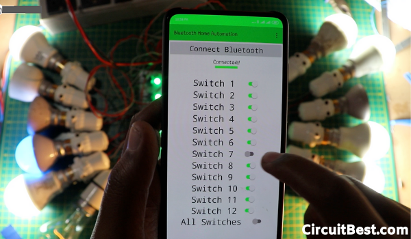
Beneath the "Interface with Bluetooth" Button, you will discover 12 Toggle catches. These flip catches are utilized for turning On/Off the Relays.
Finally yet not least I have likewise included at the same time switch. On the off chance that you press the switch, at that point all transfers will be turned on all at once.
There are largely the details of the application. Obviously, you can include more switches by including not many more Functions. In any case, I need to make the task as straightforward as could reasonably be expected.
Step 7
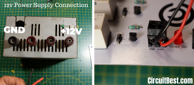
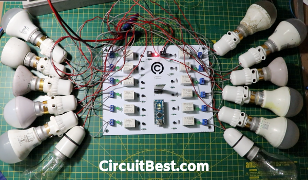
First I took 12 Holders for 12 lights. At that point, I have associated the Holders with arrangement with the hand-off. Furthermore, the association terminal will go to the mains voltage.
Right now, I have associated all the Light Holders with the transfers. Presently for the AC power Input, I have utilized one 2 pin plug and associated each of the 12 sets of wires in equal.

Comments