
How the 3V LED Dimmer Circuit works?
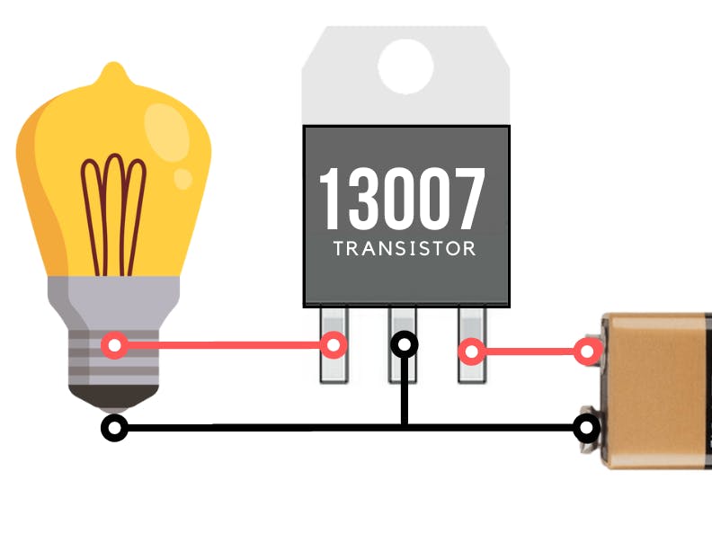
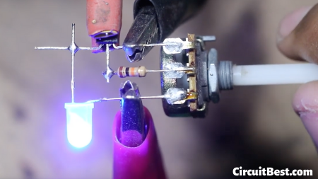
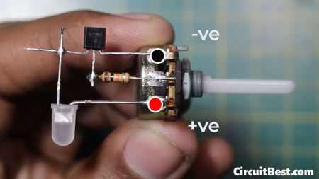
The Circuit works with the basic precept of a Transistor. The Potentiometer creates a Voltage divider inside the circuit. And whilst we rotate the Potentiometer then It creates Different voltage Levels for the LED Dimmer. These Voltage stages are sent to the Transistor’s Base with a 10k Current Limiting resistor. This resistor is important. Otherwise, the Transistor could be damaged. Now the base voltage changes. For this, the Transistor flows modern from Collector to Emitter. And The Loads that are connected with the transistor could be Powered Up. In this way, the 3v LED Circuit works.
Watch Video:Here is the video from Creative Creator approximately 3v LED Dimmer Circuit. I hope you will apprehend Everything about the circuit.
How the 3V LED Dimmer Circuit works?The Circuit works with the basic precept of a Transistor. The Potentiometer creates a Voltage divider inside the circuit. And whilst we rotate the Potentiometer then It creates Different voltage Levels for the LED Dimmer. These Voltage stages are sent to the Transistor’s Base with a 10k Current Limiting resistor. This resistor is important. Otherwise, the Transistor could be damaged. Now the base voltage changes. For this, the Transistor flows modern from Collector to Emitter. And The Loads that are connected with the transistor could be Powered Up. In this way, the 3v LED Circuit works.
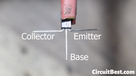
Step 1
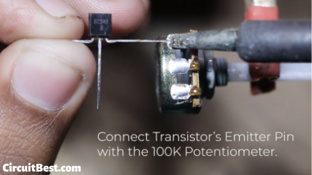
Step 2
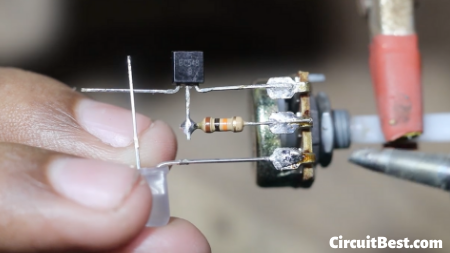
Step 3
Step 4


Comments