

Hardware components | ||||||
| × | 1 | ||||
| × | 1 | ||||
 |
| × | 4 | |||
| × | 1 | ||||
| × | 1 | ||||
| × | 1 | ||||
This project is inspired by the heroic efforts of engineers at the Fukushima Daiichi nuclear plant following the events of massive earthquake and subsequent tsunami. We have identified a primary point of interest in an this case. The issue being that the area is mapped by technicians manually which delays rescue, repair and restoration. We wanted to create a ROV/robot that can be used to navigate the terrain remotely/autonomously and create a map of the environment and relay the information back to the operator.
SLAM (Simultaneous Localization and Mapping) is a technique used for exploring unknown terrains. In some instances, a bot cannot rely on any reference (altitude or heading or GPS or maps or any other navigational aid) for guidance. For example, in a collapsed nuclear reactor, the radiation would block any external signal and the building may have been altered, making maps meaningless.
Specifications● Keeps track of location (Localization)
● Keeps track of environment (Mapping)
● Detect radiation level
● Relay information back to the base
AssumptionsThe environment is assumed to be arranged in form of a 2D grid of 32*32 cells. Each cell is assumed to be 2 feet in side and is a square. The bot is assumed to move from the center of one grid to the center of the adjacent grid. The bot can only move in any of the cardinal directions (E-W N-S), the map is constructed due North.
Localization and MappingThe primary objective of the localization is to estimate the current position of the robot based on sensor data. The primary objective of mapping is to estimate the immediate environment in the vicinity of the robot. Mapping in our case includes terrain mapping (navigable or un-navigable) and resource mapping (level of radiation, which for the sake of simplicity is just light level).
FrameworkWill upload code to github
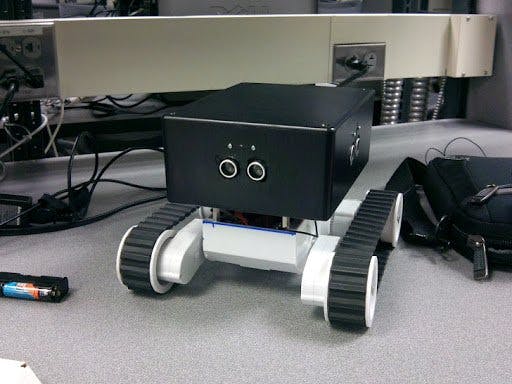
We created a new framework for the purpose of isolating the higher level and lower level functions. As a result, the Core bot routines are architecture independent and can be ported to any embedded system architecture. We created well-organized stacks for navigation, localization and communication. The level 0 drivers are architecture dependent, in this case MBed. This layer directly connects to the robot. The level 0 driver includes routines to get data from sensors, drive motors and wireless communication.
Motor DriversThe motors are driven using a four wheel differential drive mechanism. Initial analysis showed that the stall current of each motor was as high as 1.2 A. As a result a high performance motor driver was required. We chose to use four TA8080K motor drivers due to their high peak current (~3A) handling capabilities and also for their TTL inputs which allow them to be driven directly by a micro-controller.
The H-bridge ICs have two inputs, which allows four modes of operation; forwards (10), reverse (01), off (00) and brake (11). The circuit was built on a prototyping board, with four headers for motor control inputs (two inputs per side that drive both motor controllers), four pairs of motor outputs, and Vcc and ground connections.
UltrasonicThe main obstacle detection is performed using 4 HCSR04 ultrasonic rangefinder modules, one in each direction. The HCSR04 ultrasonic range finders used are specified at ranges of over 15 feet. They have a simple interface consisting of two pins, a trigger pin and an echo pin. When the trigger pin is held high for at least 10 μs, a series of ultrasonic pulses will be sent out. The return echo of these pulses will cause the echo pin to be high for a duration that varies with distance. The echo duration is 148 μs per inch. After not finding an mbed driver for this rangefinder, we wrote one that used interrupts to start and stop a timer with the rise and fall of the echo pin. This worked well for a single module, and was even easily copied to have a pair of rangefinders. The implementation into a class to encapsulate the functionality had some difficulties, specifically the proper coding to initialize the InterruptIn class and adding rise and fall events within a class. The library was completed with help from looking at the DigitalJoyStick library which uses interrupts to implement a joy stick. The library does not require the trigger function to initiate a scan due to the interrupt based readings; this allows all 4 of the modules to be triggered by a single trigger pin and command.
The 15 foot range was not seen, our maximum range shows about 30 inches, with occasional spikes up to 80 inches (< 1% of measurements). Although this is far below the listed specifications, it was enough to allow us to detect obstacles that would be in the next grid location from the robot. Further testing must be done to determine if there is some way to get a better result with these sensors.
Scanning Infrared detector (SID)The infrared detector aims to cover the blind spot of the ultrasonic sensor as in the area between the grids. The range is from 10 cms to 30 cms . The SID module includes a Sharp IR range finder placed on a pan servo (not shown in the picture). This enables the SID to view a wider area of up to 80-100 deg in front of the robot. The control was implemented on an Arduino and any obstacle was signaled via an interrupt to the main controller(Mbed).
Radiation SensorThe radiation sensor was simulated using a photodiode to measure light intensity by connecting it to an analog input on the Mbed. In reality, this payload sensor would be chosen based on the needs of the mission. Possible payload sensors include oxygen sensor, toxic gas monitoring, radiation monitoring, mine detection, or other uses where the use of a robot or ROV could protect human lives from dangerous hazards.
CommunicationsThe robot/ROV communications are handled by a Texas Instruments EZ430 RF2500 kit. The kit comes with two radio modules that are controlled by a MSP430 micro-controller and a USB host programmer that provides serial communication to a host PC. In our implementation, the MSP430s were programmed to transmit any incoming serial communications to the other radio, thus acting like a wireless serial bridge. The code used is a very slightly modified version from a lab used in EE290Q, Advanced Topics in Communication Networks at UC Berkeley, and available on the web. We modified the robot/ROV side micro controller, to use one IO pin that would be driven high upon receiving a special character ($) so that it could trigger an interrupt that would alert the robot to urgent communications. We use this interrupt to toggle between autonomous and manual controls.


_3u05Tpwasz.png?auto=compress%2Cformat&w=40&h=40&fit=fillmax&bg=fff&dpr=2)

Comments