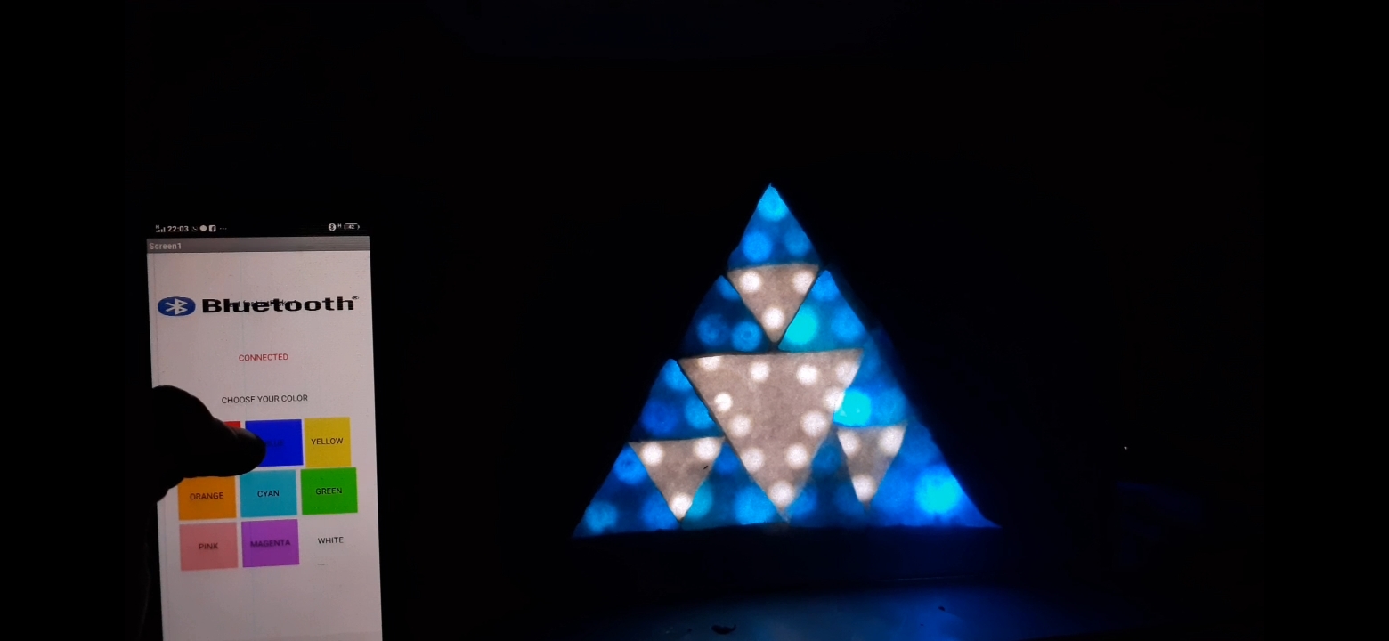
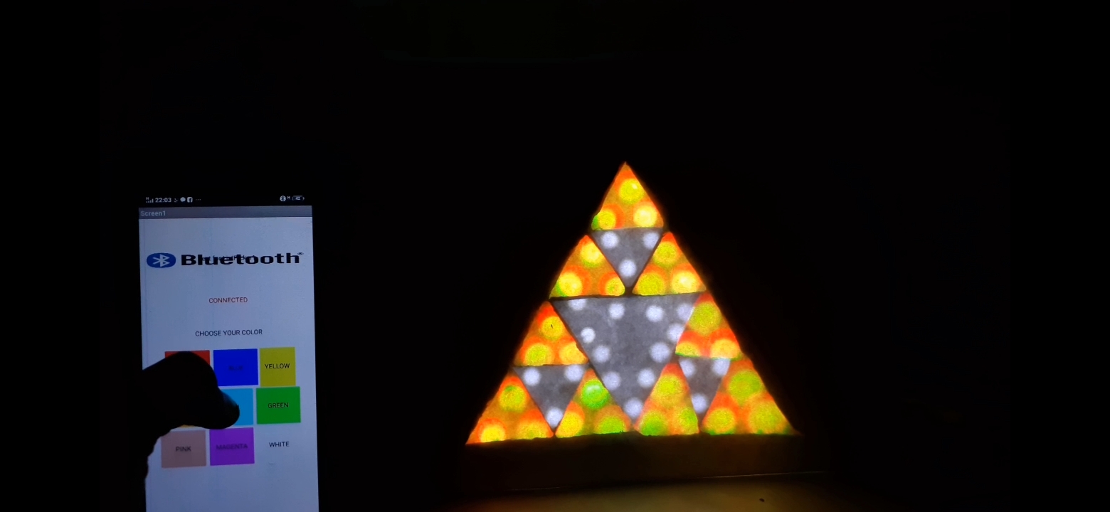
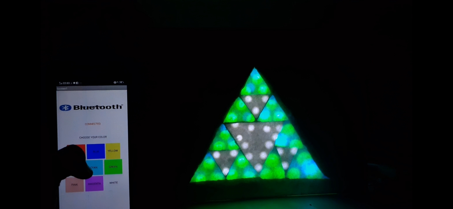
LED SHADES are awesome to watch and they mesmerize us as well as sooth our eyes and relax our brain. So in this article I will tell you how I created shades using SIERPINSKI'S TRIANGLE and your SMART PHONE via an application that you can built using HTML or CSS or any other programming language.
SO LET'S GET STARTED with the BUILD
YOU CAN ALSO GO VISIT MY CHANNEL ON YOUTUBE :GO ELECTRONICS
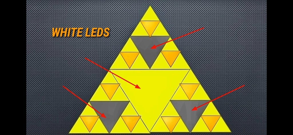
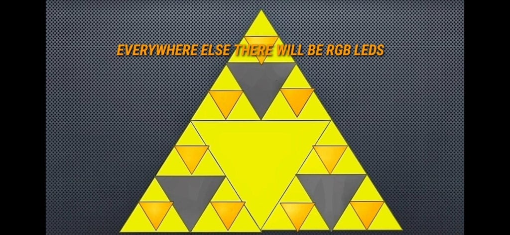
Step 1: UNDERSTANDING SIERPINSKI'S TRIANGLEFirst lets understand the concept behind sierpinski's triangle which is based on FRACTALS
Fractals are never ending pattern that are SELF-SIMILIAR across different scales.They are created by repeating
a simple process over and over in an ongoing feedback loop.
Simple to say fractals are infinite patterns and keep o going. As you can see in the image that triangle inside a triangle inside a triangle to an infinite pattern.
Now we are going off topic so lets start with the build.
NOTE ; There is animation provided in the video on my YouTube channel.
GO ELECTRONICS


Comments