

Hardware components | ||||||
_ztBMuBhMHo.jpg?auto=compress%2Cformat&w=48&h=48&fit=fill&bg=ffffff) |
| × | 1 | |||
 |
| × | 1 | |||
 |
| × | 2 | |||
 |
| × | 1 | |||
 |
| × | 2 | |||
 |
| × | 1 | |||
 |
| × | 1 | |||
I build a Studio Monitor Management project, and one part of that project is a VU meter, to display audio signal level in dBu. There are many ways to build VU meter, most common way is to use LED bulbs. However, to use LEDs will require many pins. Initially I plan to use 16 LEDs for each stereo channel, so in total there will be 32 LEDs! And those LEDs need to be controlled individually, although it is possible to use I2C serialization to reduce number of required pins to control those LEDs, it seems bit more complicated to build the electronic circuitry (PCB etching, soldering, and so on.... to me at least, being lazy to build those... :D ).
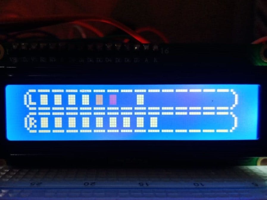
Along the way, I found a project KT Audio VU Meter by ThomAce (check on this link). which simplify the needs to display audio level by using an LCD (Liquid Crystal Display) without any complex electronic circuitry, only 3 resistors and 2 capacitors and standard PCB with holes should be enough. The number of segment is 14, which is also still close with my initial plan of using 16 LEDs.
This ProjectHere we are, this project actually is a derivative work from ThomAce's KT Audio VU Meter, with following changes:
- Audio level is measured in decibel (dBu), so it could reflect common audio metering
- Range for measurement can be adjusted easily, by changing the macro definition. Default value are -25dBu to 2dBu.
- Provides function to calibrate the VU meter, as I found the reality that the unit behaves in dynamic ways (maybe due to noises, power supply and connections, and perhaps some emotional things are involved as well :D )
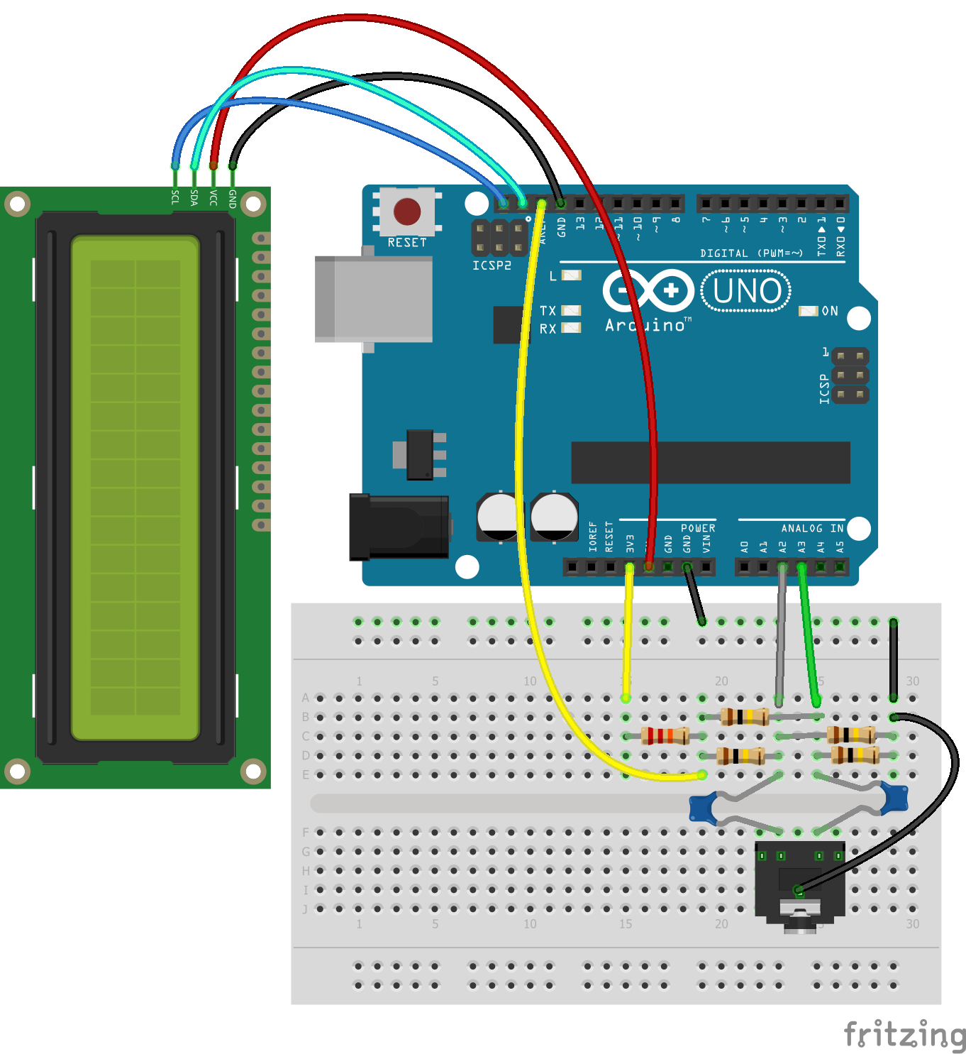
Although default values for voltage calculation parameters are provided, it is highly encouraged to perform proper voltage measurements using a multi meter at certain points (please refer to the diagram below or documentation for the calibration here).
The default values are (based on measurement in my environment):
- Reference voltage: voltage measured at
AREFpin, in millivolt (mV). Defined in macro asVREF = 1500.
- Center voltage: voltage measured at center of voltage divider (in the middle of 100K resistors), in mV, at condition the input channel is connected to ground (see documentation). Defined in macro as
VCENTER = 450.
- Offset voltage: defined in macro as
VOFFSET = 315. This value can only be displayed in Serial port, so you need to activateSerial.begin(9600)inside yourvoid setup()coding block as following (in order to see the value for offset value):
void setup() {
    Serial.begin(9600);
}
This is the sample of offset voltage value in my environment (VREF=1500, VCENTER=450). You can check Volt L and Volt R values below, in my case are 339.55mV and 335.16mV.
Volt L: 339.55mV L data: -7.16dBu Volt R: 335.16mV R data: -7.28dBu R: 10, 10 L: 10, 10
Now, you can use the value in between or average value to be used as VOFFSET (let's say 337), then call method setReference(), typically inside the setup() block, as you can see below. You can keep default values for other parameters by using VREF and VCENTER definitions.
void setup() {
    lcd.init();
    lcd.setReference(VREF, VCENTER, 337); //this will set offset to 337
}
In most cases, the following result with only several mV differences should be OK (in Volt L and Volt R) after adjusting vOffset, since it's quite hard to get exact zero difference.
Volt L: 2.48mV L data: -49.89dBu  Volt R: -4.84mV  R data: nandBu  R: 0, 0 L: 0, 0
 Volt L: -0.45mV L data: nandBu  Volt R: -3.38mV  R data: nandBu  R: 0, 0 L: 0, 0
 Volt L: 2.48mV L data: -49.89dBu  Volt R: -4.84mV  R data: nandBu  R: 0, 0 L: 0, 0
 Volt L: -1.91mV L data: nandBu  Volt R: -1.91mV  R data: nandBu  R: 0, 0 L: 0, 0
 Volt L: 2.48mV L data: -49.89dBu  Volt R: -3.38mV  R data: nandBu  R: 0, 0 L: 0, 0
To make calibration more easier without changing the code, it is possible to put a trimpot attached to other analog pin, and adjust the value of offset voltage using that trimpot, by comparing the adjusted value and actual reading value described above, until the difference is at the lowest, or you can set a LED that will goes on/off when the difference between trimpot voltage value and actual reading value is within acceptable range (let's say tenths of millivolts).


Comments