



Hardware components | ||||||
| × | 1 | ||||
 |
| × | 1 | |||
 |
| × | 1 | |||
 |
| × | 1 | |||
Software apps and online services | ||||||
| ||||||
Hand tools and fabrication machines | ||||||
 |
| |||||
 |
| |||||
| ||||||
Hidden inside many older CPUs there is a tiny temperature sensor: a transistor wired as a diode, built right onto the silicon die so the motherboard could keep an eye on the processor’s temperature. When the CPU is retired, that sensor is still there, and it still works. In this project I bring it back to life on an Intel Pentium 4 631 using nothing but a Raspberry Pi Pico and two wires: the Pico’s internal pull-up resistor powers the diode, its ADC reads the voltage, and a quick one-time calibration with a DS18B20 turns millivolts into degrees. No extra components, no motherboard just an old CPU doing a new job.
Get the datasheet. Every CPU that exposes its thermal diode documents it in its datasheet. Search for your exact model plus “datasheet” (for example “Pentium 4 631 datasheet”) and look for two signals: THERMDA (thermal diode anode) and THERMDC (thermal diode cathode). If your CPU’s datasheet doesn’t list them, the diode isn’t accessible from outside and this project won’t work with that CPU. This is the case for most CPUs made after roughly 2008–2010, which use internal digital sensors instead.
For the Intel Pentium 4 631 (Cedar Mill, 65 nm, LGA775) the reference is the Intel Pentium 4 Processor 6x1 Sequence Datasheet, document 310308. The relevant information is in section 5.2.7 “Thermal Diode”:
Inside the die, the “diode” is actually a PNP transistor: its base-emitter junction is the sensor, and its collector is tied internally to ground (V<sub>SS</sub>). From the outside it behaves like a normal silicon diode, with the anode on THERMDA and the cathode on THERMDC.
Locate the lands. LGA775 CPUs have flat gold lands instead of pins. Use the land map in the datasheet, and make sure you are reading the land-side view (looking at the bottom of the CPU), otherwise the map is mirrored. The small gold triangle on one corner of the package marks land A1. AL1 and AK1 are in the same column as A1 (column 1), but at the opposite end of that edge: starting from that corner, you find AN1, AM1, AL1 (third) and AK1 (fourth).
Test the diode with a multimeter. Before soldering anything, make sure the sensor is alive:
- Ground yourself to avoid ESD.
- Set the multimeter to diode mode.
- Put the red probe on AL1 (THERMDA) and the black probe on AK1 (THERMDC).
- Swap the probes.
Keep the test short: most multimeters test diodes with about 0.5–1 mA, which is above Intel’s 200 µA spec.
Reading
Meaning
~0.6–0.8 V red on AL1, OL reversed
✅ Diode alive, lands correctly identified
OL in both directions
Wrong lands, or poor probe contact
~0 V in both directions
Short, or wrong lands
Forward reading only with probes reversed
Anode and cathode swapped: recheck the land map
The exact value depends on your multimeter’s test current and on room temperature. For reference, at the ~40 µA used later by the Pico, my Pentium 4 631 measured 706–718 mV at room temperature. The multimeter reads a little higher because it uses a larger current.
Step 2 – Solder the wires and watch the sensor reactOnce you’ve confirmed the diode works, solder a thin wire to AL1 (THERMDA) and one to AK1 (THERMDC). The lands are small and close together, so be careful:
- use thin, flexible wire (30 AWG wire-wrap or enamelled wire is ideal), and pre-tin both the wire and the land;
- use plenty of flux, a fine soldering tip and a short contact time: just enough for the solder to flow;
- check with the multimeter (continuity mode) that AL1 and AK1 aren’t bridged to each other or to the neighbouring lands;
- secure the wires to the CPU with a drop of hot glue or epoxy a couple of centimetres from the joints, so no mechanical stress ever reaches the lands.
Now connect the multimeter to the two wires, still in diode mode (red on the AL1 wire, black on the AK1 wire), and note the reading. Then warm the metal heat spreader for a few seconds with a lighter or a hair dryer: the voltage starts to drop. When you stop heating, it slowly climbs back to its original value as the CPU cools down.
This is the key behaviour of every silicon junction: at constant current, its forward voltage decreases by about 2 mV for every °C of temperature increase. Heating the CPU by 20–30 °C gives a drop of 40–60 mV, clearly visible on any multimeter. If you see it, you’ve got a working temperature sensor.
Thanks to the copper heat spreader’s thermal mass, a few seconds of heat won’t harm the CPU or the solder joints. Just don’t overdo it: the datasheet’s storage limit is 85 °C.
Prepare the board first. Before connecting anything to the CPU, set up the Raspberry Pi Pico:
- Install MicroPython on the Pico: hold BOOTSEL while plugging in the USB cable, then in Thonny go to Tools → Options → Interpreter → Install or update MicroPython.
- Open the board’s file list in Thonny (View → Files) and make sure no other program is stored on it. Delete any old
main.py(or aboot.pyyou didn’t write). A leftover script could configure GP27 as an output and drive several milliamps into the thermal diode, far above the 200 µA limit in the datasheet. - Upload
calibration.pyandthermometer.pyto the board. - Unplug the USB cable. Never solder or wire anything with the board powered.
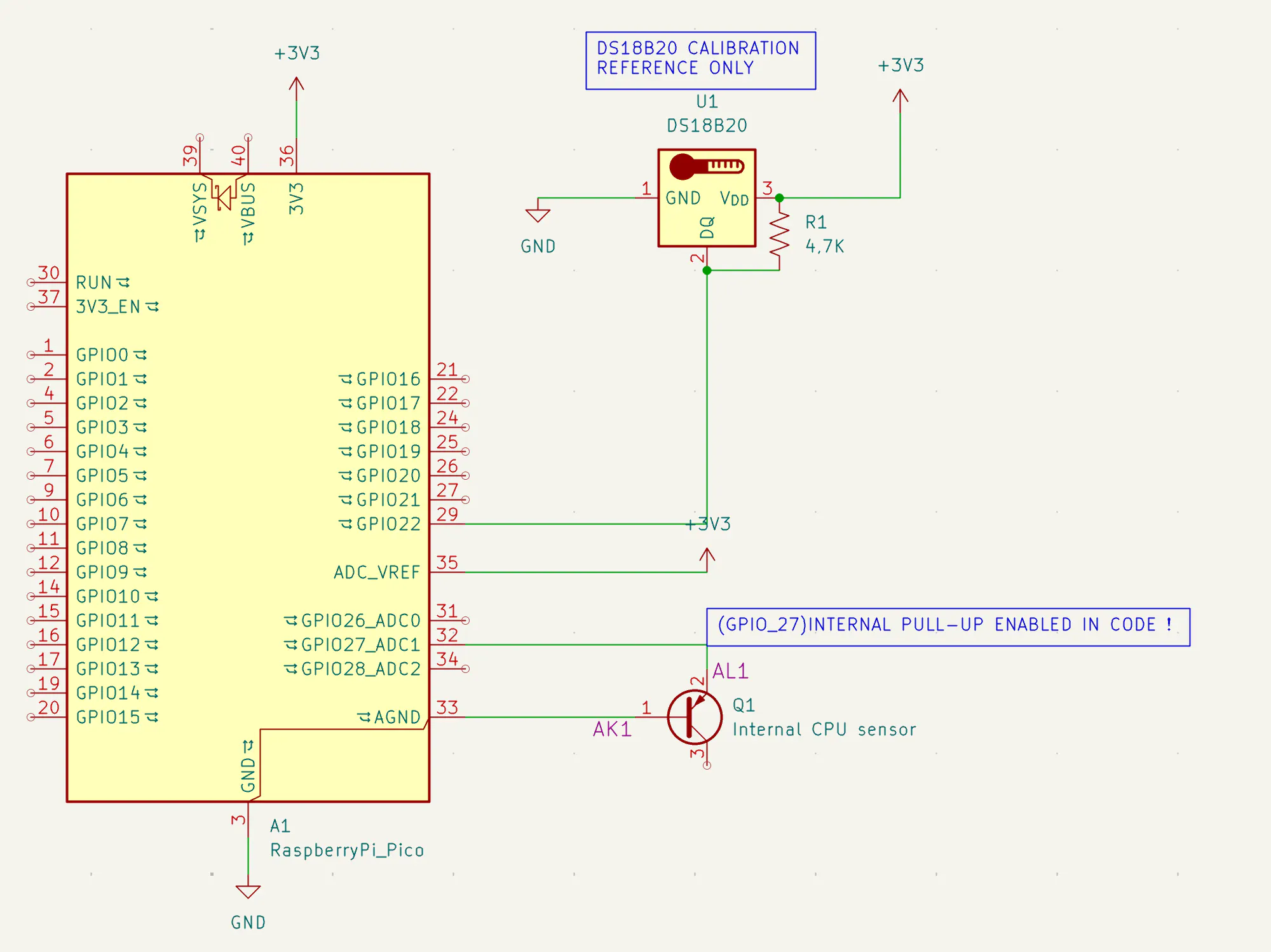
Wiring. The whole sensor needs only two wires:
+----------+-------------------+-------------------------------+
| CPU land | Signal            | Raspberry Pi Pico             |
+----------+-------------------+-------------------------------+
| AL1      | THERMDA (anode)   | GP27 / ADC1 (physical pin 32) |
| AK1      | THERMDC (cathode) | AGND        (physical pin 33) |
+----------+-------------------+-------------------------------+
GP27 and AGND sit right next to each other on the Pico header, which keeps the wires short and tidy. AGND is the ground reference dedicated to the ADC: returning the diode current there keeps the measurement cleaner than a generic GND pin.
No resistor needed: the internal pull-up. A diode used as a temperature sensor must be driven with a small, constant current. Instead of adding an external resistor, this project uses the internal pull-up resistor of the RP2040, enabled in software on the same pin that the ADC reads:
python
adc = ADC(27)
Pin(27, Pin.IN, Pin.PULL_UP)   # after ADC(): the pull-up biases the diode
The RP2040 datasheet specifies the pull-up at 50–80 kΩ, which puts the diode current comfortably within Intel’s specification:
+-----------------------------+----------------------------+
| Parameter                   | Value                      |
+-----------------------------+----------------------------+
| RP2040 pull-up resistance   | 50 - 80 kOhm (datasheet)   |
| Supply voltage              | 3.3 V                      |
| Diode forward voltage       | ~0.6 - 0.7 V               |
| Voltage across the pull-up  | ~2.7 V                     |
| Resulting diode current     | ~35 - 55 uA                |
| Intel spec (Pentium 4 6x1)  | 5 - 200 uA                 |
+-----------------------------+----------------------------+
So the same pin powers the diode, limits its current, and reads its voltage, which saves components and connections. The order of the two lines matters: initializing the ADC disables the pin’s pulls, so the pull-up must be enabled afterADC(27). Never configure GP27 as an output while the CPU is connected.
Calibration sensor (temporary). For calibration only, connect a DS18B20. The 1-Wire bus requires a 4.7 kΩ pull-up resistor between DQ and 3V3:
+-------------+---------------------------------------+
| DS18B20 pin | Raspberry Pi Pico                     |
+-------------+---------------------------------------+
| GND         | GND                                   |
| DQ          | GP22  + 4.7 kOhm resistor to 3V3      |
| VDD         | 3V3(OUT) (physical pin 36)            |
+-------------+---------------------------------------+
The DS18B20 and its resistor can be removed once calibration is done.
Using a Pico clone? Check ADC_VREF. The RP2040’s ADC uses the ADC_VREF pin as its voltage reference. If it isn’t connected, every reading is meaningless, usually close to full scale. The official Pico takes care of it, but some compatible boards don’t.
+------------------------------+----------------------+---------------------------------------+
| Board                        | ADC_VREF (pin 35)    | Action                                |
+------------------------------+----------------------+---------------------------------------+
| Raspberry Pi Pico (official) | Connected to 3V3     | None                                  |
|                              | via 200 Ohm          |                                       |
| YD-RP2040 and some clones    | NOT connected        | Connect ADC_VREF to 3V3 (pin 36),     |
|                              |                      | ideally through 200-220 Ohm           |
+------------------------------+----------------------+---------------------------------------+
| Quick check: ADC(4) (internal temperature sensor) should read ~0.7 V.                       |
| If it reads ~3.3 V, ADC_VREF is not connected.                                              |
+----------------------------------------------------------------------------Why calibration is needed. Every thermal diode is slightly different. Intel measured each CPU at the factory and stored a correction value (Tdiode_Offset) in an internal register, but that register can only be read while the CPU is running on a motherboard. On a retired CPU, we have to calibrate it ourselves. The good news: it takes a single measurement and is done only once.
A. Measure your 3V3 rail. The RP2040’s ADC uses its own supply as reference, so the code needs to know its exact value. Connect the Pico to your PC, run any script (for example diag.py), and measure the voltage between the 3V3(OUT) pin and GND with a multimeter. Write the value in VREF, using all the digits your meter shows, in both calibration.py and thermometer.py:
python
VREF = 3.287 # <-- your measured valueEvery 10 mV of error on VREF shifts the reading by about 1 °C. This is the only line you need to edit:
+--------------+------------------------------------+--------------------------------+
| Setting      | Where                              | When to change it              |
+--------------+------------------------------------+--------------------------------+
| VREF         | calibration.py, thermometer.py     | Always: your measured 3V3      |
| DIODE_PIN    | calibration.py, thermometer.py     | Only if you don't use GP27     |
| DS_PIN       | calibration.py                     | Only if you don't use GP22     |
| SETTLE_MIN   | calibration.py                     | Optional: default 5 minutes    |
+--------------+------------------------------------
B. Place the DS18B20 on the CPU. Put the flat face of the DS18B20 on the metal heat spreader, with a drop of thermal paste, and hold it in place with a piece of tape. Cover the CPU and the sensor with a cloth to protect them from drafts.
C. Run calibration.py and don’t touch anything. The script:
- checks that the diode is connected (initial Vf between 200 and 800 mV);
- waits 5 minutes with a countdown, so the CPU and the DS18B20 reach the same temperature;
- takes 30 readings of both sensors and averages them into a single calibration point;
- warns you if the temperature drifted by more than 0.2 °C during the measurement;
- computes the full curve and saves it as
cal.jsonon the Pico’s flash.
- How one point is enough. A single measurement gives one point of the curve: the diode voltage V<sub>be0</sub> at the temperature T<sub>0</sub>. The rest of the curve comes from the physics of a silicon junction:
V<sub>be</sub>(T) = V<sub>G0</sub> − (V<sub>G0</sub> − V<sub>be0</sub>) · T/T<sub>0</sub> − η · (kT/q) · ln(T/T<sub>0</sub>)
where V<sub>G0</sub> ≈ 1.205 V is the silicon bandgap voltage extrapolated to 0 K, η ≈ 3, k is Boltzmann’s constant, q is the electron charge, and temperatures are in kelvin. Around room temperature this gives a slope of about −1.9 to −2 mV/°C. The script turns the equation into a curve from 0 to 85 °C and stores it in cal.json.
Expected accuracy. Near the calibration temperature the result is as good as the DS18B20 reference. Further away, it relies more on the model:
+------------------------------------------+------------------------+
| Distance from calibration temperature    | Expected accuracy      |
+------------------------------------------+------------------------+
| within +/- 10 °C                         | about +/- 1 °C         |
| +/- 20 °C                                | about +/- 2 °C         |
| +/- 40 °C                                | a few °C               |
+------------------------------------------+------------------------+
For room temperature monitoring, calibrating at room temperature is ideal. When the calibration is done, you can remove the DS18B20: from now on, the CPU is the sensor.
Step 5 – Use it as a thermometerOnce cal.json has been saved, the calibration is done for good. Remove the DS18B20 and its 4.7 kΩ resistor: from now on, only the two CPU wires are needed.
+----------+-------------------+-------------------------------+
| CPU land | Signal            | Raspberry Pi Pico             |
+----------+-------------------+-------------------------------+
| AL1      | THERMDA (anode)   | GP27 / ADC1 (physical pin 32) |
| AK1      | THERMDC (cathode) | AGND        (physical pin 33) |
+----------+-------------------+-------------------------------+
Run thermometer.py. Open it in Thonny and press F5. At startup the script loads cal.json from the Pico’s flash, enables the internal pull-up on GP27 and starts printing the temperature once per second. Each reading is the average of 1000 ADC samples, which keeps the noise at about ±0.1 °C:
If you run it before calibrating, it stops with “cal.json not found: run calibration.py first”.
See it as a graph. In Thonny, open View → Plotter: the printed values are drawn live as a chart. Warm the CPU with your hand or a hair dryer and watch the curve rise, then fall slowly as the heat spreader cools down.
Start automatically at power-up. To use the CPU as a standalone thermometer, save thermometer.py on the board a second time with the name main.py. MicroPython runs main.py automatically at every boot, so the Pico starts measuring as soon as it’s powered, even from a USB charger. cal.json stays on the flash, so there’s no need to calibrate again.
What the messages mean:
+------------------------------------------+------------------------------------------------+
| Message                                  | Meaning / what to do                           |
+------------------------------------------+------------------------------------------------+
| 23.42 °C                                 | Normal reading                                 |
| ... ! outside 0-85 °C range              | Vf outside the calibrated curve: reading less  |
|                                          | reliable                                       |
| Diode not detected (Vf ... mV)           | Wire detached or swapped: check AL1 -> GP27    |
|                                          | and AK1 -> AGND, then run diag.py              |
| cal.json not found                       | Run calibration.py first                       |
+------------------------------------------+------------------------------------------------+
When to recalibrate. The calibration is tied to that CPU, that board and that 3V3 rail. Run calibration.py again if you change CPU or board. If you only change the power supply, measuring the new 3V3 and updating VREF in thermometer.py is enough.
+--------------------------------------+-----------------------------------------------+
| What changed                         | What to do                                    |
+--------------------------------------+-----------------------------------------------+
| Nothing                              | Nothing: cal.json is kept on the flash        |
| Different power supply / USB port    | Measure 3V3 again and update VREF             |
| Different Pico board                 | Update VREF and run calibration.py again      |
| Different CPU                        | Run calibration.py again                      |
+--------------------------------------This is a simple two-wire setup, so it’s worth knowing where its limits are and how to push them further.
Thermal inertia of the heat spreader. The diode sits on the silicon die, under the CPU’s copper heat spreader (IHS). The IHS adds thermal mass, so the reading follows quick temperature changes with a delay of a few minutes. For room temperature monitoring this doesn’t matter, because ambient temperature changes slowly. It’s also why the calibration waits 5 minutes: the CPU and the DS18B20 must reach the same temperature.
If you need a faster response, you could delid the CPU, removing the IHS to expose the die. Be aware that on most LGA775 Pentium 4s the IHS is soldered to the die: delidding requires heat and care, and a cracked die means a dead sensor. Without the IHS, the die is also fragile and must be handled gently. Try it only on a spare CPU.
The 3V3 rail is the reference. The RP2040’s ADC measures relative to its own supply. A 1% change on the 3V3 rail shifts the diode reading by about 6 mV, which is roughly 3 °C. That’s why VREF must be measured, and why you should keep the same power supply you calibrated with.
Accuracy of the one-point calibration. The slope of the curve is calculated from the physics of the silicon junction, not measured, so accuracy decreases further from the calibration temperature.
+-------------------------------+---------------------------+-----------------------------------+
| Error source                  | Typical effect            | How to reduce it                  |
+-------------------------------+---------------------------+-----------------------------------+
| 3V3 rail drift                | ~3 °C per 1% of change    | Same power supply; LM4040 on      |
|                               |                           | ADC_VREF                          |
| DS18B20 reference             | +/- 0.5 °C                | Better reference sensor           |
| IHS thermal inertia           | Delay of a few minutes    | Wait before reading; delid        |
| One-point model slope         | Grows with distance from  | Multi-point calibration           |
|                               | calibration temperature   |                                   |
| ADC noise                     | ~0.1 °C (1000 samples)    | Already averaged in the code      |
+-------------------------------+---------------------------+-----------------------------------+
Possible improvements:
+-------------------------------+---------------------------------------------------------+
| Improvement                   | What it gives                                           |
+-------------------------------+---------------------------------------------------------+
| LM4040 3.0 V on ADC_VREF      | Stable reference, independent of the 3V3 rail           |
| Multi-point calibration       | Measured slope instead of calculated: better accuracy  |
| (e.g. room temp + warm step)  | over a wider range                                      |
| Remote diode sensor IC        | Dedicated ADC, series resistance cancellation, I2C      |
| (TMP451, EMC1412, MAX6642)    | output, about +/- 1 °C without calibration              |
| Delid                         | Faster thermal response                               |
+-------------------------------+So, that old Pentium 4 sitting in a drawer? Turns out it still had a job to do. 🌡️ With a Raspberry Pi Pico, two wires and zero extra components, it’s now a working thermometer. No motherboard, no fan: just a CPU with a brand-new purpose, doing it pretty well. The best part? It’s not just my Pentium 4. Any CPU that exposes THERMDA and THERMDC can do the same trick. So open that drawer full of old hardware and check the datasheets: there might be a temperature sensor waiting for a second life. If you build one, I’d love to see it! Share a photo and tell me which CPU you used. And if you find one with an even weirder hidden sensor, let me know in the comments.


Comments