

Hardware components | ||||||
| × | 1 | ||||
 |
| × | 1 | |||
 |
| × | 1 | |||
| × | 1 | ||||
Software apps and online services | ||||||
| ||||||
I've always been a fan of FM radio and, driving around Austin I'm constantly hitting the presets on my car radio to hear the latest tunes. Many stations now use the Radio Data System to show the current song's title and artist on the car radio. I've always wanted a to see a list of what was playing on each station so I built a gadget to do that using a Raspberry Pi and two Silicon Graphics Si4703 FM Receiver chips. One FM receiver connects to the car Aux audio input. The other constantly scans specified FM stations and sends the station's current artist and title to an Android app running on my phone using the phone's wifi hotspot, where I can select that station.
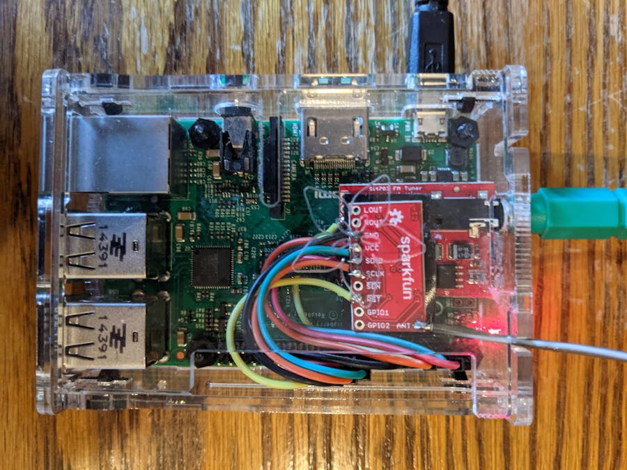
HardwareI'm using a Pi 2 Model B v1.1 with a freshly installed Raspbian GNU/Linux 10 (buster) OS enclosed in an Adafruit (adafruit.com) Pi Box Plus ($12.50). For the Si4703 chip, I used two products from SparkFun (sparkfun.com), their FM Tuner Evaluation Board (WRL-12938, $21.95) and their FM Tuner Basic Breakout (BOB-11083, $10.95). The evaluation board adds an audio output, whose cable also serves as the FM antenna. For the breakout board I just used a 2' wire for the antenna. You can see the Pi in its case in the picture below along with it's microUSB power connector. I drilled a hole in the side of the case for the audio cable and brought the second antenna wire out through one of the slots in the case.
The two FM chips are connected via the I2C (Inter-Integrated Circuit) serial bus. The basic Pi has I2C data and clock lines on physical pins 3 and 5. Thanks to JJ Slabbert (https://www.instructables.com/Raspberry-PI-Multiple-I2c-Devices) for instructions on how to add the second I2C bus. With those modifications to the OS the FM receiver cards are wired to the Pi as follows:
Bus 1 (SparkFun FM Tuner Evaluation Board)
- 3.3V Power (physical pin 1) --> Si4703 3.3V
- SDA GPIO (BCM GPIO 2 - physical pin 3) --> Si4703 SDIO
- SCL GPIO (BCM GPIO 3 - physical pin 5) --> Si4703 SCLK
- Reset GPIO (BCM GPIO 4 - physical pin 7) --> Si4703 ~RST
- Ground (physical pin 9) --> Si4703 GND
Bus 3 (SparkFun FM Tuner Basic Breakout)
- 3.3V Power (physical pin 17) --> Si4703 3.3V
- SDA GPIO (BCM GPIO 23 - physical pin 16) --> Si4703 SDIO
- SCL GPIO (BCM GPIO 24 - physical pin 18) --> Si4703 SCLK
- Reset GPIO (BCM GPIO 25 - physical pin 22) --> Si4703 ~RST
- Ground (physical pin 25) --> Si4703 GND
For the Python programming I am indebted to two coders I found online. Pi Flyer (see thread at https://www.raspberrypi.org/forums/viewtopic.php?f=41&t=28920&start=25&sid=eb677d15d2577540ab9e7f68ce76b35a) figured out how to initialize the Si4703 with recent Pi hardware and software (it's tricky because you have to use the SDA GPIO to hold the SDIO low while transitioning the RST pin from low to high and then reset the SDA GPIO to its I2C function). And KansasCoder (see https://www.raspberrypi.org/forums/viewtopic.php?t=28920) figured out how to read and write to the Si4703 registers (tricky as well because the READ actually WRITES one of the key registers).
Once you get the Si4703 connected properly and get the hang of communicating with it (suggestion: keep a shadow copy of the Si4703 registers and use that every time you go to write a new register) it's pretty straightforward to program the Si4703 using these Silicon Labs datasheets:
- Programming guide: https://www.silabs.com/documents/public/application-notes/AN230.pdf
- Registers: https://www.silabs.com/documents/public/data-sheets/Si4702-03-C19.pdf
The program si4703_play_one_command_line.py reads the i2c bus number of the desired radio, station frequency and volume (1 is good for earphones, 15 for speakers) from the command line, plays the station on the radio attached to the specified I2C bus and exits without stopping the radio.
In that program I include verbose comments describing the Si4703 registers and how to read and write them, as well as functions to initialize the I2C bus, decode a register given a register number and the bit address of the desired parameter (taken right from the Silicon Labs documents), update the shadow register and write a register, functions that I use throughout all my programs.
In every program I create a Python list, shadow_register, for the 12 writeable registers (the low and high bytes of the Si4703 registers 2 through 7), initially set to 12 zeroes. For every write to a register I read the current register set using the I2C read command (being aware of the fact that the read actually writes the high byte of register 2), update the shadow register with the value I wish to write, and then use the I2C write command to write the complete shadow register out.
With those pieces in place the code to start the radio and set the volume and frequency is fairly simple and follows the Power Configuration Sequence on p. 12 of AN230.pdf.
Acquiring the RadioText and RadioTextPlusThe Radio Data System includes things like program type and traffic data. I am interested in the RadioText (RT) which displays the station's information and song artist and title if one is playing (what you often see on your car radio) and, in some cases, the RadioTextPlus (RT+),which calls out where in the RadioText string the artist and title are. Decoding the RDS accurately is fairly complicated and I'm still not 100% sure I am doing it correctly. The program si4703_rds_all.py uses the basic functions described above to start the radio on the specified I2C bus in play mode at the specified volume and reads a file containing the frequencies you want to scan repeatedly for their RT and RT+.
The format of the frequencies file is simple. A sample file (from here in Austin) is:
freqs = [93.7, 97.1, 98.1, 98.5, 98.9, 100.1, 100.7]
freqs_with_RT_plus = [98.1, 100.7]
The first line is required. The second line is not. (To determine which stations support RT+ I just ran the code with lots of print statements to see what each station was actually transmitting).
Acquiring the RDS data is spelled out in https://www.silabs.com/documents/public/application-notes/AN243.pdf. Also, you can request the RDS Technical Specification (R19/019_1) from the RDS Forum (http://www.rds.org.uk/2010/RDS-Specification.htm).
The format of RT+ is described in https://www.radioworld.com/news-and-business/lets-demystify-rds-radio-text-plus and https://tech.ebu.ch/docs/techreview/trev_307-radiotext.pdf.
The RT (and other info) is sent in 16-bit words in RDSA, RDSB, RDSC, RDSD in registers 0xC, 0xD, 0xE and 0xF.
RDSA and RDSB contain the Program Identifier (PI) or station ID and Group Type Code (what type of data is being sent - RT, traffic, etc.). When the Group Type Code is 2 the RT is read in 4-character segments as Unicode characters from RDSC and RDSD.
RT segment index (RDSB (Reg 0xD) [0-3]) 0 indicates the start of the RT. The end of the RT transmission is shown by either a carriage return (decimal 13) as one of the 4 characters, a blank line (4 decimal 32 characters), or reaching the 15th segment (there are a maximum of 64 characters in the RT).
If an unprintable character comes up in the RT I replace it with a blank. For the most part the text is readable but there appear to be more glitches in the text than would be seen in a car FM radio display. Perhaps it's because I'm ignoring registers which indicate when there are errors in the RDS stream, or because I am using a piece of wire as my antenna rather than the roof-mounted antenna in my car.
If an RT isn't found within a specified timeout (which I set to 15 seconds) I go on to the next frequency in the list.
Once the RT is found I go look for the RT+ info if the station is in the list of frequencies that include RT+ data. The RT+ can be pulled from the RDS stream when a specific Applications Identification (0x4BD7) appears in RDSD (register 0xF) and the Group Type is 0xC. The RT+ data show which two items (such as artist and title) are in the string and where in the string that item begins and ends. From this I pull out the artist and title.
If there is no RT+ I attempt to parse the artist and title directly from the RT string. Many stations, for example, consistently use an RT of <title> by <artist> on <station>. You just have to look at a lot of RTs to see the patterns.
Once I have the artist and title I print them to standard output along with a time stamp and the frequency. A typical output is:
Wednesday 01/27/21 17:24:15:   93.7  Bob-FM The Rock Of Austin
Wednesday 01/27/21 17:24:19:   97.1  Austin City Limits Radio
Wednesday 01/27/21 17:24:26: 98.1 98.1 KVET On My Way To You Cody JohnsonThe RDS scanner program described above is nice (if you let it run for awhile you can generate detailed playlists of all your favorite stations) but what I really want to do is to be able to listen to those stations in real time while driving around in my car. So that's why I needed two radio chips: one to scan the dial and show me what's playing and the other to play my latest selection.
To accomplish this I needed three pieces:
First, I needed the Pi to run headless while sitting in the console of my car, physically connected only to the Aux stereo input of my car radio and to a microUSB power supply, playing the selected station over the Aux input and using the other radio to scan the dial and read the RDS data.
Second, I needed an Android app running on my phone showing me what was playing on each station and giving me the ability to select that station.
Third, I needed a method for the Pi and phone to communicate.
To solve the first problem, I created a version of si4703_play_one_command_line.py, si4703_player.py that reads a file, freq_vol.txt, containing the specified frequency and volume (example format: 98.1<space>15) in a loop, playing the specified station at the specified volume. I start this automatically upon bootup of the Pi by putting the call in /etc/rc.local:
/usr/bin/python3 /home/pi/si4703/si4703_player.py 1 &I also created a version of si4703_rds_all.py, si4703_rds_to_file.py, that writes just the frequency, artist and title to a file, artist_title.txt.
Next, I created an Android app, ScanRDS, that talks with the Raspberry Pi via wifi using the phone's hotspot, reads the output of si4703_rds_to_file.py and writes the artist and title to five different buttons. When a button is pressed, the app communicates with the Pi to play that station using the first radio. For good measure, I added four settable presets since some of your favorite stations may not readily update their RDS info.
Why is Luke Combs in yellow? He's on my list of favorite artists. When si4703_rds_to_file.py finds an artist on that list it puts an asterisk next to it. When the ScanRDS program sees an artist/title string with an asterisk it writes it in yellow and beeps to get my attention.
Finally, to communicate between the Android app and the Pi I created a simple REST (representational state transfer) server on the Pi using Flask and used the Android Volley package on the phone to send requests to it.
Flask is a Linux utility that enables you to create a REST server (in this case, on the Pi), that will respond to GET or POST HTTP requests (which can be sent with a curl command) from a REST client (in this case the Android app running on my phone).
The REST commands are specified in a Python program, si4703_rest_server.py:
- playradio: when used with a GET command, returns the currently playing station, and when used with a POST command changes the station:
GET: curl <IP address of Pi>:5000/playradio       # Returns current station
POST: curl -d "freqvol=100.1 10" -X POST <IP address of Pi>:5000/playradio # Set station to 100.1 with volume 10- startrds: starts the RDS scan program si4703_rds_to_file.py
- getrds: reads the bottom line of the artist_title.txt file output from si4703_rds_to_file.py to get the latest artist/title combo found
The Android app issues the GET/POST commands using the Android Volley package.
The si4703_rest_server.py program is not started with the usual python program invocation. Instead, one tells Flask which program to run, then starts Flask. This all should be done in the /etc/rc.local file on the Pi, which looks like this (including the previously mentioned si4703_player.py program):
export FLASK_APP=/home/pi/si4703/si4703_rest_server.py
/usr/bin/flask run --host=0.0.0.0 &
/usr/bin/python3 /home/pi/si4703/si4703_player.py 1 &
With all these pieces in place, I can see on my phone what is playing on each of my favorite stations and then switch to that station just by clicking on the button. Or I can play one of my preset stations if nothing appeals to me. The Pi is sitting in my car's center console, running headless, so it starts whenever I start my car, and starts playing whatever station is in the freq_vol.txt file. Then it connects to my phone where I can run ScanRDS.
I added one more Android app, FindStations, which uses the Si4703's SEEK function to find and display the 20 strongest FM stations. This is useful when you are on the road and get to a new city and want to find out what stations are there. To do this I added another Python program using the same basic functions as the other ones, si4703_seek.py, and added a section to si4703_rest_server.py to run that program. I also grab the Program Type (PTY) from the RDS stream and send that as well (although its not always accurate). On my Android phone in Austin the app looks like:
The complete Android code is on Github (https://github.com/DaveJaffe/ScanRDS and FindStations).
Hope this document helps you play with the Si4703. I certainly found a lot of help through Googling to figure this all out. Please contact me with any questions!
si4703_play_one_command_line.py
PythonSyntax: python si4703_play_one_command_line.py ic2_bus frequency(MHz) volume
# Connects Silicon Labs Si4703 radio receiver (from Sparkfun kit WRL-12938) with Raspberry Pi 2 Model B v1.1
# si4703_play_one_command_line.py: reads specified frequency and volume from command line, plays station, exits without powering down
# Syntax: python si4703_play_one_command_line.py i2c_bus frequency(MHz) volume
# Dave Jaffe
# January 2021

# Silicon Labs Documentation:
# Operating instructions: https://www.silabs.com/documents/public/application-notes/AN230.pdf (AN230)
# Registers: https://www.silabs.com/documents/public/data-sheets/Si4702-03-C19.pdf (Si4702-03-C19)

# Register read/write information from KansasCoder (see https://www.raspberrypi.org/forums/viewtopic.php?t=28920)
# Initialization based on Pi Flyer in thread at
#   https://www.raspberrypi.org/forums/viewtopic.php?f=41&t=28920&start=25&sid=eb677d15d2577540ab9e7f68ce76b35a

import sys
import RPi.GPIO as GPIO
import smbus
from time import time, sleep
import subprocess
from os import path

def main():
  # Check correct number of arguments, read them
  if (len(sys.argv) != 4):
    print("Syntax: python si4703_play_one_command_line.py i2c_bus frequency(MHz) volume")
    exit(-1)
  else:
    i2c_bus = int(sys.argv[1])
    freq = float(sys.argv[2])
    volume = int(sys.argv[3])
    print("Playing radio on i2c bus %d with frequency %5.1f and volume %d" % (i2c_bus, freq, volume))

  initialize_si4703(i2c_bus)
  i2c = smbus.SMBus(i2c_bus)
  address = 0x10 #address of SI4703

  # Si4703 contains 32 8-bit integers, each corresponding to a byte of a 16-bit word:
  # reg = i2c.read_i2c_block_data(address, value, 32) returns them as:
  # 0A high, 0A low ... 0F high, 0F low, 00 high, 00 low .. 09 high, 09 low
  # We will combine high and low bytes since Silicon Labs register spec refers to entire 16-bit word
  # The mapping between a register number reg_no and the location of its high byte in reg is
  # ind = 2 * ((16 + (reg_no - 0xA)) % 16)

  # NOTE about register reads:
  # i2c.read_i2c_block_data(address, value, 32) also WRITES value to Reg 2 high
  # as discovered by KansasCoder (see https://www.raspberrypi.org/forums/viewtopic.php?t=28920)
  # Thus we must always keep track of Reg 2 high, and then send it as i2c.read_i2c_block_data 2nd parameter
  # We will define
  # shadow_register = reg[16:28]   # Reg 2 high, 2 low, ... 7 high, 7 low (only Reg 2 - 7 are writeable)
  # to keep track of the current value of the registers and read it before every write
  # So reads will use:
  # reg = i2c.read_i2c_block_data(address, shadow_register[0], 32)
  # The function decode_reg(reg, reg_no, low_bit, high_bit) is used to pull a certain value from reg using the bits specified in the Si Labs spec

  # NOTE about register writes:
  # i2c.write_i2c_block_data(address, value, byte_list) writes value to Reg 2 high and then the list to 2 low, 3 high, 3 low etc.
  # where value is an 8-bit byte (expressed as an integer) and byte_list is the list of 8-bit bytes
  # We will use shadow register described above for the write as follows:
  # i2c.write_i2c_block_data(address, shadow_register[0], shadow_register[1:])
  # So to do a write (this is done in write_register):
  # reg = i2c.read_i2c_block_data(address, shadow_register[0], 32)             # Read current register
  # shadow_register = reg[16:28]                                               # Copy current register values 2 - 7 into shadow register
  # update_shadow_register(shadow_register, reg_no, low_bit, high_bit, value)  # Update shadow_register reg_no[low_bit:high_bit] with value
  # i2c.write_i2c_block_data(address, shadow_register[0], shadow_register[1:]) # Write register

# print("Initial Register Readings")
# reg = i2c.read_i2c_block_data(address, 0, 32)  # Nothing in Reg 2 high set yet
# print("Register 00h - Device ID Part Number: " + hex(decode_reg(reg, 0x00, 12, 14)))
# print("Register 00h - Device ID Manufacturer ID: " + hex(decode_reg(reg, 0x00, 0, 11)))

  # Follow AN230 Powerup Configuration Sequence (p. 12)
  # Set the XOSCEN bit (Reg 7 [15]) to power up the crystal
  shadow_register = [0] * 12    # Nothing in Reg 2 high set yet
  shadow_register = write_register(i2c, address, shadow_register, 7, 15, 15, 1)
  print("Powering up the crystal")
  #  Wait for crystal to power up (required for crystal oscillator operation), minimum 500 ms
  sleep(.5)
  print("Crystal now powered up")

  # Set DMUTE Reg 2 [14] to disable mute and ENABLE Reg 2 [0] to set the powerup state
  print("Powering up the device")
  shadow_register = write_register(i2c, address, shadow_register, 2, 14, 14, 1)
  shadow_register = write_register(i2c, address, shadow_register, 2, 0, 0, 1)
  #  Wait for device to powerup
  sleep(.1)
  print("Device now powered up")

  # VOLUME (Reg 5 [0-3]):
  # 0x1 (1) is the lowest (good for earphones), 0xF (15) is the highest (good for speakers)
  shadow_register = write_register(i2c, address, shadow_register, 5, 0, 3, volume)

  # To tune the desired station write channel to CHAN (Reg 3 [0-9]) and set TUNE (Reg 3 [15])
  # Channel is defined as an integer representing how many steps it is above minimum
  # FM regional frequency given regional spacing
  SPACE = .2       # US spacing between FM stations in MHz
  MIN_FREQ = 87.5  # US minimum FM frequency in MHz
  channel = round((freq - MIN_FREQ) / SPACE)
  shadow_register = write_register(i2c, address, shadow_register, 3, 0, 9, channel)
  shadow_register = write_register(i2c, address, shadow_register, 3, 15, 15, 1)


def initialize_si4703(bus):
  # Initialization based on Pi Flyer in thread at
  #   https://www.raspberrypi.org/forums/viewtopic.php?f=41&t=28920&start=25&sid=eb677d15d2577540ab9e7f68ce76b35a
  # To add a 2nd i2c bus, see
  #   https://www.instructables.com/Raspberry-PI-Multiple-I2c-Devices/
  #
  # Wiring chart:
  # Bus 1
  # SDA GPIO   (wired to Si4703 SDIO)  BCM GPIO 2 (physical pin 3)
  # SCL GPIO   (wired to Si4703 SCLK)  BCM GPIO 3 (physical pin 5)
  # Reset GPIO (wired to Si4703 ~RST)  BCM GPIO 4 (physical pin 7)
  # Bus 3
  # SDA GPIO   (wired to Si4703 SDIO)  BCM GPIO 23 (physical pin 16)
  # SCL GPIO   (wired to Si4703 SCLK)  BCM GPIO 24 (physical pin 18)
  # Reset GPIO (wired to Si4703 ~RST)  BCM GPIO 25 (physical pin 22)

  if (bus == 1):
    sda_gpio = 2
    scl_gpio = 3
    rst_gpio = 4
  if (bus == 3):
    sda_gpio = 23
    scl_gpio = 24
    rst_gpio = 25

  # Set the GPIO module to reference BCM pin numbers
  GPIO.setmode(GPIO.BCM)
  GPIO.setwarnings(False)

  # Setup Reset GPIO as output
  GPIO.setup(rst_gpio, GPIO.OUT)

  # Setup SDA GPIO as output
  # It needs to temporarily act as output to set the Si4703 to 2-wire (i2c) mode
  # Then we will set it back to i2c SDA
  GPIO.setup(sda_gpio, GPIO.OUT)

  # The Si4703 requires the following sequence to set it's busmode to 2-wire (i2c):
  # Hold the SDIO pin low while the RST pin transitions from low to high
  GPIO.output(sda_gpio, GPIO.LOW)
  sleep(.1) #allow pin to settle
  GPIO.output(rst_gpio, GPIO.LOW)
  sleep(.1)
  GPIO.output(rst_gpio, GPIO.HIGH)
  sleep(.1)

  # Setup SDA GPIO back to i2c SDA line
  # Make use of the subprocess module to execute the gpio program included
  # with WiringPi from the Raspbian commandline.
  # 'gpio' is the program to be executed, and the rest are options
  # '-g' is a flag that causes pin numbers to be interpreted as BCM_GPIO
  # 'mode' is the option used to select the mode of the pin
  # 'sda_gpio' is the pin to change the mode of
  # 'ALT0' is the alternate pin mode code for i2c
  subprocess.check_output(['gpio', '-g', 'mode', str(sda_gpio), 'ALT0'])

def decode_reg(reg, reg_no, low_bit, high_bit):
  # Added by Dave Jaffe
  # get latest set of register values with: reg = i2c.read_i2c_block_data(address, value, 32)
  # Use low_bit, high_bit from Si4702-03-C19 spec
  # For example: CHANNEL (Reg 3 [0-9]) would be decoded from reg: decode_reg(reg, 3, 0, 9)
  # We will combine high and low bytes since Silicon Labs register spec refers to entire 16-bit word

  # reg byte layout: 0A high, 0A low ... 0F high, 0F low, 00 high, 00 low .. 09 high, 09 low
  # The mapping between a register number reg_no and the location of its high byte in reg is
  ind = 2 * ((16 + (reg_no - 0xA)) % 16)
  H = reg[ind]      # Register high byte
  L = reg[ind + 1]  # Register low byte
  W = 256*H + L     # Register 16-bit word
  # Use bit mask to pull desired bits, return them as an integer
  mask_len = high_bit - low_bit + 1
  mask = 2**mask_len - 1
  return (((mask << low_bit) & W) >> low_bit)

def update_shadow_register(shad_reg, reg_no, low_bit, high_bit, value):
  # Added by Dave Jaffe
  # Set shadow_register values
  # Use low_bit, high_bit from Si4702-03-C19 spec
  # For example, to set CHANNEL (Reg 3 [0-9]) update_shadow_register(shadow_register, 3, 0, 9, channel)
  # We will combine high and low bytes since Silicon Labs register spec refers to entire 16-bit word

  # shadow_register layout: Reg 2 high, 2 low, ... 7 high, 7 low (only Reg 2 - 7 are writeable)
  # The mapping between a register number reg_no and the location of its high byte in shadow_register is
  ind = (reg_no-2) * 2
  H = shad_reg[ind]      # Register high byte
  L = shad_reg[ind + 1]  # Register low byte
  W = 256*H + L     # Register 16-bit word
# print(format(W, '016b'))
  # First, set bits where new value will go to 0 with a negative mask
  mask_len = high_bit - low_bit + 1
  mask = 2**mask_len - 1
  mask = mask << low_bit
  W = W & ~mask
  # Next, move new value to proper bit and add it to W
  V = value << low_bit
  W = W  + V
  # Break up W into H and L and write to shadow_register
  H = W >> 8
  L = W & 2**8 - 1
  shad_reg[ind] = H
  shad_reg[ind + 1] = L

def write_register(i2c, address, shad_reg, reg_no, low_bit, high_bit, value):
  reg = i2c.read_i2c_block_data(address, shad_reg[0], 32)
  shad_reg = reg[16:28]
  update_shadow_register(shad_reg, reg_no, low_bit, high_bit, value)
  i2c.write_i2c_block_data(address, shad_reg[0], shad_reg[1:])
  return (shad_reg)

if __name__ == "__main__":
  main()
si4703_rds_all.py
PythonSyntax: python si4703_rds_all.py ic2_bus volume freqs_file
# Connects Silicon Labs Si4703 radio receiver (from Sparkfun kit WRL-12938) with Raspberry Pi 2 Model B v1.1
# si4703_rds_all.py - scan specified frequencies, playing station and printing out RadioText and RadioTextPlus
# Syntax: python si4703_rds_all.py i2c_bus volume freqs_file

# Silicon Labs Documentation:
# Operating instructions: https://www.silabs.com/documents/public/application-notes/AN230.pdf (AN230)
# Registers: https://www.silabs.com/documents/public/data-sheets/Si4702-03-C19.pdf (Si4702-03-C19)

# Register read/write information from KansasCoder (see https://www.raspberrypi.org/forums/viewtopic.php?t=28920)
# Initialization based on Pi Flyer in thread at
#   https://www.raspberrypi.org/forums/viewtopic.php?f=41&t=28920&start=25&sid=eb677d15d2577540ab9e7f68ce76b35a

import sys
from os import path
import RPi.GPIO as GPIO
import smbus
from time import time, sleep
from datetime import datetime
import subprocess


def main():

  # Check correct number of arguments, read them
  if (len(sys.argv) != 4):
    print("Syntax: python si4703_rds_all.py i2c_bus volume freqs_file")
    exit(-1)
  else:
    i2c_bus = int(sys.argv[1])
    volume = int(sys.argv[2])
    freqs_file = sys.argv[3]
    print("Scanning specified frequencies from file %s on radio on i2c bus %d with volume %d" % (freqs_file, i2c_bus, volume))

  # Check for frequencies file
  if not path.exists(freqs_file):
    print('Need file ' + freqs_file); exit()
  else:
    f_freqs = open(freqs_file, "r")

  initialize_si4703(i2c_bus)
  i2c = smbus.SMBus(i2c_bus)
  address = 0x10 #address of SI4703

  # Si4703 contains 32 8-bit integers, each corresponding to a byte of a 16-bit word:
  # reg = i2c.read_i2c_block_data(address, value, 32) returns them as:
  # 0A high, 0A low ... 0F high, 0F low, 00 high, 00 low .. 09 high, 09 low
  # We will combine high and low bytes since Silicon Labs register spec refers to entire 16-bit word
  # The mapping between a register number reg_no and the location of its high byte in reg is
  # ind = 2 * ((16 + (reg_no - 0xA)) % 16)

  # NOTE about register reads:
  # i2c.read_i2c_block_data(address, value, 32) also WRITES value to Reg 2 high
  # as discovered by KansasCoder (see https://www.raspberrypi.org/forums/viewtopic.php?t=28920)
  # Thus we must always keep track of Reg 2 high, and then send it as i2c.read_i2c_block_data 2nd parameter
  # We will define
  # shadow_register = reg[16:28]   # Reg 2 high, 2 low, ... 7 high, 7 low (only Reg 2 - 7 are writeable)
  # to keep track of the current value of the registers and read it before every write
  # So reads will use:
  # reg = i2c.read_i2c_block_data(address, shadow_register[0], 32)
  # The function decode_reg(reg, reg_no, low_bit, high_bit) is used to pull a certain value from reg using the bits specified in the Si Labs spec

  # NOTE about register writes:
  # i2c.write_i2c_block_data(address, value, byte_list) writes value to Reg 2 high and then the list to 2 low, 3 high, 3 low etc.
  # where value is an 8-bit byte (expressed as an integer) and byte_list is the list of 8-bit bytes
  # We will use shadow register described above for the write as follows:
  # i2c.write_i2c_block_data(address, shadow_register[0], shadow_register[1:])
  # So to do a write (this is done in function write_register):
  # reg = i2c.read_i2c_block_data(address, shadow_register[0], 32)             # Read current register
  # shadow_register = reg[16:28]                                               # Copy current register values 2 - 7 into shadow register
  # update_shadow_register(shadow_register, reg_no, low_bit, high_bit, value)  # Update shadow_register reg_no[low_bit:high_bit] with value
  # i2c.write_i2c_block_data(address, shadow_register[0], shadow_register[1:]) # Write register

  # Follow AN230 Powerup Configuration Sequence (p. 12)
  # Set the XOSCEN bit (Reg 7 [15]) to power up the crystal
  shadow_register = [0] * 12    # Nothing in Reg 2 high set yet
  shadow_register = write_register(i2c, address, shadow_register, 7, 15, 15, 1)

  print("Powering up the crystal")
  #  Wait for crystal to power up (required for crystal oscillator operation), minimum 500 ms
  sleep(.5)
  print("Crystal now powered up")

  # Set DMUTE Reg 2 [14] to disable mute and ENABLE Reg 2 [0] to set the powerup state
  print("Powering up the device")
  shadow_register = write_register(i2c, address, shadow_register, 2, 14, 14, 1)
  shadow_register = write_register(i2c, address, shadow_register, 2, 0, 0, 1)
  #  Wait for device to powerup
  sleep(.1)
  print("Device now powered up")

  # VOLUME (Reg 5 [0-3]):
  # 0x1 (1) is the lowest (good for earphones), 0xF (15) is the highest (good for speakers)
  shadow_register = write_register(i2c, address, shadow_register, 5, 0, 3, volume)

  # Enable RDS (Reg 4 [12])
  # See https://www.silabs.com/documents/public/application-notes/AN243.pdf for RDS reception details
  # See http://www.interactive-radio-system.com/docs/EN50067_RDS_Standard.pdf for Radiotext (RT) details
  shadow_register = write_register(i2c, address, shadow_register, 4, 12, 12, 1)
  print("RDS Enabled")

  # Parse frequencies file
  # Format:
  # freqs = [93.7, 97.1, 98.1, 98.5, 98.9, 100.1, 100.7]
  # freqs_with_RT_plus = [96.7, 98.1, 100.7]             - optional
  freqs = []
  freqs_with_RT_plus = []
  freqs_line = f_freqs.readline()
  if (len(freqs_line) == 0):
    print('No frequencies specified')
    f_freqs.close()
    exit(-1)
  freqs = eval(freqs_line[freqs_line.index('['):])
  freqs_with_RT_plus_line = f_freqs.readline()
  if (len(freqs_with_RT_plus_line) != 0):
    freqs_with_RT_plus = eval(freqs_with_RT_plus_line[freqs_with_RT_plus_line.index('['):])
  print('Freqs to scan = ' + str(freqs))
  print('Freqs with RT_plus = ' + str(freqs_with_RT_plus))

  # Start scanning frequencies for RDS and RDS_plus info
  time_out_sec = 15
  while (True):
    for freq in freqs:
#     print('\n' + ('%5.1f' % (freq)))
      # To tune the desired station write channel to CHAN (Reg 3 [0-9]) and set TUNE (Reg 3 [15])
      # Channel is defined as an integer representing how many steps it is above minimum
      # FM regional frequency given regional spacing
      SPACE = .2       # US spacing between FM stations in MHz
      MIN_FREQ = 87.5  # US minimum FM frequency in MHz
      channel = round((freq - MIN_FREQ) / SPACE)
      shadow_register = write_register(i2c, address, shadow_register, 3, 0, 9, channel)
      shadow_register = write_register(i2c, address, shadow_register, 3, 15, 15, 1)
      sleep(1)
      # Unset TUNE (Reg 3 [15]) to be able to retune
      shadow_register = write_register(i2c, address, shadow_register, 3, 15, 15, 0)
      sleep(1)

      # Obtain Radio Text (RT)
      # RT (and other info) is sent in 16-bit words in RDSA, RDSB, RDSC, RDSD in reg C, D, E and F
      # RDSA and RDSB indicate the Program Identifier (PI) or station ID and Group Type Code
      # (what type of data is being sent - RT, traffic, etc.)
      # The RT is read in 4-character segments from unicode characters from RDSC and RDSD
      # The RT segment index (RDSB (Reg D) [0-3]) segment 0 indicates the start of the RT
      # The end of the RT transmission is shown by either a carriage return (CR - decimal 13) as one of the 4 chars,
      # a blank line (4 decimal 32 chars), or reaching the 15th segment (max 64 chars in RT)
      s_prev = ''             # The previously decoded string
      RT = ''                 # The RT string being built
      seen_RT_seg0 = False    # Whether the RT segment 0 has been seen yet
      found_RT = False        # Whether we've found the RT string yet
      no_RT = False           # If no RT found before timeout
      RT_start_time = time()
      artist = ''
      title = ''
      prev_seg_ind = -1
      while(not found_RT):
        reg = i2c.read_i2c_block_data(address, shadow_register[0], 32)
        if (decode_reg(reg, 0x0D, 12, 15) == 0x2):    # Wait for RDSB (reg D) [12-15] to show Group Type 0x2 => Radio Text (Group 2A)
          seg_ind = decode_reg(reg, 0x0D, 0, 3)           # RT segment index
#         print(seg_ind)
          if ((seg_ind != 0) and (not seen_RT_seg0)):
            if (time() - RT_start_time) > time_out_sec:   # Bail if no RT within time_out_sec seconds
#             print('No RT segment 0 found within ' + str(time_out_sec) + ' sec')
              no_RT = True
              break
            else:
              continue                                    # Wait for RT segment 0
          else:
            seen_RT_seg0 = True
            if (seg_ind == prev_seg_ind + 1):             # Next RT segment
              CH = decode_reg(reg, 0x0E, 8, 15)           # Pull 4 unicode chars as integers from RDSC and RDSD
              CL = decode_reg(reg, 0x0E, 0, 7)
              DH = decode_reg(reg, 0x0F, 8, 15)
              DL = decode_reg(reg, 0x0F, 0, 7)
              if (CH in range(32,127)): chrCH = chr(CH)   # Unicode character corresponding to integer
              else: chrCH = ' '                           # Replace non-printing chars with blanks
              if (CL in range(32,127)): chrCL = chr(CL)
              else: chrCL = ' '
              if (DH in range(32,127)): chrDH = chr(DH)
              else: chrDH = ' '
              if (DL in range(32,127)): chrDL = chr(DL)
              else: chrDL = ' '
              s = chrCH + chrCL + chrDH + chrDL
              if (s != s_prev):                           # If this is a new piece of the string add it to the RT
                RT = RT + s
              s_prev = s
#             print(CH, CL, DH, DL)
#             print(str(seg_ind) + s)
              if (CH == 13 or CL == 13 or DH == 13 or DL == 13 or seg_ind == 15 or (CH == 32 and CL == 32 and DH == 32 and DL == 32)):
                found_RT = True
#               print(RT)
                prev_seg_ind = -1
              else:
                prev_seg_ind = seg_ind
            if (time() - RT_start_time) > time_out_sec:   # Bail if no RT within time_out_sec seconds
#             print('RT not complete within ' + str(time_out_sec) + ' sec')
              no_RT = True
              break
        elif (time() - RT_start_time) > time_out_sec:   # Bail if no Group 2A within time_out_sec seconds
#         print('No Group 2A found within ' + str(time_out_sec) + ' sec')
          no_RT = True
          break

      if (no_RT == False):
#       print("Time to find RadioText: %5.1f sec" % (time() - RT_start_time))
        # Now that we've found RT find RT+ data for those stations known to have it,
        # which shows where in the RT string the song title and artist are
        # For RT_plus format see https://tech.ebu.ch/docs/techreview/trev_307-radiotext.pdf
        if (freq in freqs_with_RT_plus):
          found_RT_plus = False       # Whether we've found the RT+ info
          RTplus_start_time = time()
          while (not found_RT_plus):
            reg = i2c.read_i2c_block_data(address, shadow_register[0], 32)
            # Group 3 indicates that this transmission includes the Applications Identification (AID) for an Open Data Applications (ODA)
            #   You can verify with: print(decode_reg(reg, 0x0D, 12, 15))
            # RDSD (reg F) = 0x4bd7 is the AID for RT+ and RDSB bits 4 - 1 = 0xc indicates ODA type RT+
            if ((hex(decode_reg(reg, 0x0F, 8, 15)) == '0x4b') and (hex(decode_reg(reg, 0x0F, 0, 7)) == '0xd7') and (hex(decode_reg(reg, 0x0D, 1, 4)) == '0xc')):
#             print('0x4bd7 seen')
              while(not found_RT_plus):
                reg = i2c.read_i2c_block_data(address, shadow_register[0], 32)
                # If the Group Type is 0xc then we have RT+ data
                if (hex(decode_reg(reg, 0x0D, 12, 15)) == '0xc'):
                  item_toggle_bit =  decode_reg(reg, 0x0D, 4, 4)       # Item toggle bit - toggled when new item starts - not used here
                  item_running_bit = decode_reg(reg, 0x0D, 3, 3)       # Item running bit - toggled when item is running - not used here
                  item1_type  = decode_reg(reg, 0x0E, 13, 15)          # Item 1 type:  4 = artist   1 = song title
                  item1_start = decode_reg(reg, 0x0E, 7, 12)
                  item1_end   = decode_reg(reg, 0x0E, 1, 6)
                  item2_type  = decode_reg(reg, 0x0F, 11, 15)          # Item 2 type:  4 = artist   1 = song title
                  item2_start = decode_reg(reg, 0x0F, 5, 10)
                  item2_end   = decode_reg(reg, 0x0F, 0, 4)
                  if (item1_type == 4):
                    artist = RT[item1_start : 1 + item1_start + item1_end]
                  elif (item2_type == 4):
                    artist = RT[item2_start : 1 + item2_start + item2_end]
                  if (item1_type == 1):
                    title = RT[item1_start : 1 + item1_start + item1_end]
                  elif (item2_type == 1):
                    title = RT[item2_start : 1 + item2_start + item2_end]
                  elif (item1_type != 1 and item1_type != 4 and item2_type != 1 and item1_type != 4):
#                   print('RT+ does not contain title or artist')
                    pass
                  found_RT_plus = True
            elif (time() - RTplus_start_time) > time_out_sec:   # Bail if no RT+ within time_out_sec seconds
#             print('No RT+ found within ' + str(time_out_sec) + ' sec')
              break
        else:    # Parse artist and title from RT if they're not in RT+
          # Search RT for "by" or "/", split into title and artist
          if (RT.find('by') > -1):
            title = RT[:RT.find('by')-1]
            artist = RT[RT.find('by')+3:]
            # Strip out "now" or "on" from artist
            if (artist.find(' now ') > -1):
              artist = artist[:artist.find(' now ')]
            if (artist.find(' on ') > -1):
              artist = artist[:artist.find(' on ')]
            # Strip out "Now Playing" from title
            if (title.find('Now Playing ') > -1):
              title = title[title.find('Now Playing ')+12:]
          elif (RT.find('/') > -1):
            artist = RT[:RT.find('/')]
            title = RT[RT.find('/')+2:]
            # Strip out "now" or "on" from artist
            if (artist.find(' now ') > -1):
              artist = artist[:artist.find(' now ')]
            if (artist.find(' on ') > -1):
              artist = artist[:artist.find(' on ')]
            # Strip out "Now Playing" from title
            if (title.find('Now Playing ') > -1):
              title = title[title.find('Now Playing ')+12:]

      # Output info
      if (RT == ''):
        output = ('%5.1f' % (freq))
      elif ((artist == '') and (title == '')):
        output = ('%5.1f' % (freq)) + '  ' + RT
      elif ((artist != '') and (title == '')):
        output = ('%5.1f' % (freq)) + '  ' + artist
      elif ((artist != '') and (title != '')):
        output = ('%5.1f' % (freq)) + '  ' + artist + '   ' + title
      print(datetime.now().strftime("%A %D %H:%M:%S") + ':  ' + output)


def initialize_si4703(bus):
  # Initialization based on Pi Flyer in thread at
  #   https://www.raspberrypi.org/forums/viewtopic.php?f=41&t=28920&start=25&sid=eb677d15d2577540ab9e7f68ce76b35a
  # To add a 2nd i2c bus, see
  #   https://www.instructables.com/Raspberry-PI-Multiple-I2c-Devices/
  #
  # Wiring chart:
  # Bus 1
  # SDA GPIO   (wired to Si4703 SDIO)  BCM GPIO 2 (physical pin 3)
  # SCL GPIO   (wired to Si4703 SCLK)  BCM GPIO 3 (physical pin 5)
  # Reset GPIO (wired to Si4703 ~RST)  BCM GPIO 4 (physical pin 7)
  # Bus 3
  # SDA GPIO   (wired to Si4703 SDIO)  BCM GPIO 23 (physical pin 16)
  # SCL GPIO   (wired to Si4703 SCLK)  BCM GPIO 24 (physical pin 18)
  # Reset GPIO (wired to Si4703 ~RST)  BCM GPIO 25 (physical pin 22)

  if (bus == 1):
    sda_gpio = 2
    scl_gpio = 3
    rst_gpio = 4
  if (bus == 3):
    sda_gpio = 23
    scl_gpio = 24
    rst_gpio = 25

  # Set the GPIO module to reference BCM pin numbers
  GPIO.setmode(GPIO.BCM)
  GPIO.setwarnings(False)

  # Setup Reset GPIO as output
  GPIO.setup(rst_gpio, GPIO.OUT)

  # Setup SDA GPIO as output
  # It needs to temporarily act as output to set the Si4703 to 2-wire (i2c) mode
  # Then we will set it back to i2c SDA
  GPIO.setup(sda_gpio, GPIO.OUT)

  # The Si4703 requires the following sequence to set it's busmode to 2-wire (i2c):
  # Hold the SDIO pin low while the RST pin transitions from low to high
  GPIO.output(sda_gpio, GPIO.LOW)
  sleep(.1) #allow pin to settle
  GPIO.output(rst_gpio, GPIO.LOW)
  sleep(.1)
  GPIO.output(rst_gpio, GPIO.HIGH)
  sleep(.1)

  # Setup SDA GPIO back to i2c SDA line
  # Make use of the subprocess module to execute the gpio program included
  # with WiringPi from the Raspbian commandline.
  # 'gpio' is the program to be executed, and the rest are options
  # '-g' is a flag that causes pin numbers to be interpreted as BCM_GPIO
  # 'mode' is the option used to select the mode of the pin
  # 'sda_gpio' is the pin to change the mode of
  # 'ALT0' is the alternate pin mode code for i2c
  subprocess.check_output(['gpio', '-g', 'mode', str(sda_gpio), 'ALT0'])

def decode_reg(reg, reg_no, low_bit, high_bit):
  # Added by Dave Jaffe
  # get latest set of register values with: reg = i2c.read_i2c_block_data(address, value, 32)
  # Use low_bit, high_bit from Si4702-03-C19 spec
  # For example: CHANNEL (Reg 3 [0-9]) would be decoded from reg: decode_reg(reg, 3, 0, 9)
  # We will combine high and low bytes since Silicon Labs register spec refers to entire 16-bit word

  # reg byte layout: 0A high, 0A low ... 0F high, 0F low, 00 high, 00 low .. 09 high, 09 low
  # The mapping between a register number reg_no and the location of its high byte in reg is
  ind = 2 * ((16 + (reg_no - 0xA)) % 16)
  H = reg[ind]      # Register high byte
  L = reg[ind + 1]  # Register low byte
  W = 256*H + L     # Register 16-bit word
  # Use bit mask to pull desired bits, return them as an integer
  mask_len = high_bit - low_bit + 1
  mask = 2**mask_len - 1
  return (((mask << low_bit) & W) >> low_bit)

def update_shadow_register(shad_reg, reg_no, low_bit, high_bit, value):
  # Added by Dave Jaffe
  # Set shadow_register values
  # Use low_bit, high_bit from Si4702-03-C19 spec
  # For example, to set CHANNEL (Reg 3 [0-9]) update_shadow_register(shadow_register, 3, 0, 9, channel)
  # We will combine high and low bytes since Silicon Labs register spec refers to entire 16-bit word

  # shadow_register layout: Reg 2 high, 2 low, ... 7 high, 7 low (only Reg 2 - 7 are writeable)
  # The mapping between a register number reg_no and the location of its high byte in shadow_register is
  ind = (reg_no-2) * 2
  H = shad_reg[ind]      # Register high byte
  L = shad_reg[ind + 1]  # Register low byte
  W = 256*H + L     # Register 16-bit word
# print(format(W, '016b'))
  # First, set bits where new value will go to 0 with a negative mask
  mask_len = high_bit - low_bit + 1
  mask = 2**mask_len - 1
  mask = mask << low_bit
  W = W & ~mask
  # Next, move new value to proper bit and add it to W
  V = value << low_bit
  W = W  + V
  # Break up W into H and L and write to shadow_register
  H = W >> 8
  L = W & 2**8 - 1
  shad_reg[ind] = H
  shad_reg[ind + 1] = L

def write_register(i2c, address, shad_reg, reg_no, low_bit, high_bit, value):
  reg = i2c.read_i2c_block_data(address, shad_reg[0], 32)
  shad_reg = reg[16:28]
  update_shadow_register(shad_reg, reg_no, low_bit, high_bit, value)
  i2c.write_i2c_block_data(address, shad_reg[0], shad_reg[1:])
  return (shad_reg)

if __name__ == "__main__":
  main()
si4703_player.py
PythonSyntax: python si4703_player.py i2c_bus
freq_vol.txt example: 98.1 15
# Connects Silicon Labs Si4703 radio receiver (from Sparkfun kit WRL-12938) with Raspberry Pi 2 Model B v1.1
# si4703_player.py: reads specified frequency and volume from file, plays station, checks file in loop
# Syntax: python si4703_player.py i2c_bus

# Silicon Labs Documentation:
# Operating instructions: https://www.silabs.com/documents/public/application-notes/AN230.pdf (AN230)
# Registers: https://www.silabs.com/documents/public/data-sheets/Si4702-03-C19.pdf (Si4702-03-C19)

import sys
import RPi.GPIO as GPIO
import smbus
from time import time, sleep
import subprocess
from os import path

def main():
  # Check correct number of arguments, read them
  if (len(sys.argv) != 2):
    print("Syntax: python si4703_player.py i2c_bus")
    exit(-1)
  else:
    i2c_bus = int(sys.argv[1])
    print("Playing radio on i2c bus %d" % (i2c_bus))

  initialize_si4703(i2c_bus)
  i2c = smbus.SMBus(i2c_bus)
  address = 0x10 #address of SI4703

  # Si4703 contains 32 8-bit integers, each corresponding to a byte of a 16-bit word:
  # reg = i2c.read_i2c_block_data(address, value, 32) returns them as:
  # 0A high, 0A low ... 0F high, 0F low, 00 high, 00 low .. 09 high, 09 low
  # We will combine high and low bytes since Silicon Labs register spec refers to entire 16-bit word
  # The mapping between a register number reg_no and the location of its high byte in reg is
  # ind = 2 * ((16 + (reg_no - 0xA)) % 16)

  # NOTE about register reads:
  # i2c.read_i2c_block_data(address, value, 32) also WRITES value to Reg 2 high
  # as discovered by KansasCoder (see https://www.raspberrypi.org/forums/viewtopic.php?t=28920)
  # Thus we must always keep track of Reg 2 high, and then send it as i2c.read_i2c_block_data 2nd parameter
  # We will define
  # shadow_register = reg[16:28]   # Reg 2 high, 2 low, ... 7 high, 7 low (only Reg 2 - 7 are writeable)
  # to keep track of the current value of the registers and read it before every write
  # So reads will use:
  # reg = i2c.read_i2c_block_data(address, shadow_register[0], 32)
  # The function decode_reg(reg, reg_no, low_bit, high_bit) is used to pull a certain value from reg using the bits specified in the Si Labs spec

  # NOTE about register writes:
  # i2c.write_i2c_block_data(address, value, byte_list) writes value to Reg 2 high and then the list to 2 low, 3 high, 3 low etc.
  # where value is an 8-bit byte (expressed as an integer) and byte_list is the list of 8-bit bytes
  # We will use shadow register described above for the write as follows:
  # i2c.write_i2c_block_data(address, shadow_register[0], shadow_register[1:])
  # So to do a write (this is done in write_register):
  # reg = i2c.read_i2c_block_data(address, shadow_register[0], 32)             # Read current register
  # shadow_register = reg[16:28]                                               # Copy current register values 2 - 7 into shadow register
  # update_shadow_register(shadow_register, reg_no, low_bit, high_bit, value)  # Update shadow_register reg_no[low_bit:high_bit] with value
  # i2c.write_i2c_block_data(address, shadow_register[0], shadow_register[1:]) # Write register

  # Follow AN230 Powerup Configuration Sequence (p. 12)
  # Set the XOSCEN bit (Reg 7 [15]) to power up the crystal
  shadow_register = [0] * 12    # Nothing in Reg 2 high set yet
  shadow_register = write_register(i2c, address, shadow_register, 7, 15, 15, 1)
  print("Powering up the crystal")
  #  Wait for crystal to power up (required for crystal oscillator operation), minimum 500 ms
  sleep(.5)
  print("Crystal now powered up")

  # Set DMUTE Reg 2 [14] to disable mute and ENABLE Reg 2 [0] to set the powerup state
  print("Powering up the device")
  shadow_register = write_register(i2c, address, shadow_register, 2, 14, 14, 1)
  shadow_register = write_register(i2c, address, shadow_register, 2, 0, 0, 1)
  #  Wait for device to powerup
  sleep(.1)
  print("Device now powered up")

  # Read frequency and volume from freq_vol.txt in continuous loop
  if not path.exists("/home/pi/si4703/freq_vol.txt"):
    print("Need file freq_vol.txt"); exit()

  prev_freq =  0.0
  prev_volume = 0
  while True:
    f_freq_vol = open("/home/pi/si4703/freq_vol.txt", "r")
    freq_vol = f_freq_vol.readline()
    f_freq_vol.close()
    if (len(freq_vol) == 0):
      sleep(1)
      continue
    freq_vol = freq_vol.lstrip()  # Remove leading blank if any
    space_ind = freq_vol.find(' ')
    freq = float(freq_vol[:space_ind])
    if (freq == 0.0): break
    volume = int(freq_vol[space_ind+1:])
#   print('Playing station %5.1f at volume %d' % (freq, volume))

    if ((freq != prev_freq) or (volume != prev_volume)):
      # VOLUME (Reg 5 [0-3]):
      # 0x1 (1) is the lowest (good for earphones), 0xF (15) is the highest (good for speakers)
      shadow_register = write_register(i2c, address, shadow_register, 5, 0, 3, volume)

      # To tune the desired station write channel to CHAN (Reg 3 [0-9]) and set TUNE (Reg 3 [15])
      # Channel is defined as an integer representing how many steps it is above minimum
      # FM regional frequency given regional spacing
      SPACE = .2       # US spacing between FM stations in MHz
      MIN_FREQ = 87.5  # US minimum FM frequency in MHz
      channel = round((freq - MIN_FREQ) / SPACE)
      shadow_register = write_register(i2c, address, shadow_register, 3, 0, 9, channel)
      shadow_register = write_register(i2c, address, shadow_register, 3, 15, 15, 1)

      prev_freq = freq
      prev_volume = volume
      # Unset TUNE (Reg 3 [15]) to be able to retune
      shadow_register = write_register(i2c, address, shadow_register, 3, 15, 15, 0)
      sleep(1) # Then return to top of while loop and check freq_vol.txt for a new freq/vol

# End main()

def initialize_si4703(bus):
  # Initialization based on Pi Flyer in thread at
  #   https://www.raspberrypi.org/forums/viewtopic.php?f=41&t=28920&start=25&sid=eb677d15d2577540ab9e7f68ce76b35a
  # To add a 2nd i2c bus, see
  #   https://www.instructables.com/Raspberry-PI-Multiple-I2c-Devices/
  #
  # Wiring chart:
  # Bus 1
  # SDA GPIO   (wired to Si4703 SDIO)  BCM GPIO 2 (physical pin 3)
  # SCL GPIO   (wired to Si4703 SCLK)  BCM GPIO 3 (physical pin 5)
  # Reset GPIO (wired to Si4703 ~RST)  BCM GPIO 4 (physical pin 7)
  # Bus 3
  # SDA GPIO   (wired to Si4703 SDIO)  BCM GPIO 23 (physical pin 16)
  # SCL GPIO   (wired to Si4703 SCLK)  BCM GPIO 24 (physical pin 18)
  # Reset GPIO (wired to Si4703 ~RST)  BCM GPIO 25 (physical pin 22)

  if (bus == 1):
    sda_gpio = 2
    scl_gpio = 3
    rst_gpio = 4
  if (bus == 3):
    sda_gpio = 23
    scl_gpio = 24
    rst_gpio = 25

  # Set the GPIO module to reference BCM pin numbers
  GPIO.setmode(GPIO.BCM)
  GPIO.setwarnings(False)

  # Setup Reset GPIO as output
  GPIO.setup(rst_gpio, GPIO.OUT)

  # Setup SDA GPIO as output
  # It needs to temporarily act as output to set the Si4703 to 2-wire (i2c) mode
  # Then we will set it back to i2c SDA
  GPIO.setup(sda_gpio, GPIO.OUT)

  # The Si4703 requires the following sequence to set it's busmode to 2-wire (i2c):
  # Hold the SDIO pin low while the RST pin transitions from low to high
  GPIO.output(sda_gpio, GPIO.LOW)
  sleep(.1) #allow pin to settle
  GPIO.output(rst_gpio, GPIO.LOW)
  sleep(.1)
  GPIO.output(rst_gpio, GPIO.HIGH)
  sleep(.1)

  # Setup SDA GPIO back to i2c SDA line
  # Make use of the subprocess module to execute the gpio program included
  # with WiringPi from the Raspbian commandline.
  # 'gpio' is the program to be executed, and the rest are options
  # '-g' is a flag that causes pin numbers to be interpreted as BCM_GPIO
  # 'mode' is the option used to select the mode of the pin
  # 'sda_gpio' is the pin to change the mode of
  # 'ALT0' is the alternate pin mode code for i2c
  subprocess.check_output(['gpio', '-g', 'mode', str(sda_gpio), 'ALT0'])

def decode_reg(reg, reg_no, low_bit, high_bit):
  # Added by Dave Jaffe
  # get latest set of register values with: reg = i2c.read_i2c_block_data(address, value, 32)
  # Use low_bit, high_bit from Si4702-03-C19 spec
  # For example: CHANNEL (Reg 3 [0-9]) would be decoded from reg: decode_reg(reg, 3, 0, 9)
  # We will combine high and low bytes since Silicon Labs register spec refers to entire 16-bit word

  # reg byte layout: 0A high, 0A low ... 0F high, 0F low, 00 high, 00 low .. 09 high, 09 low
  # The mapping between a register number reg_no and the location of its high byte in reg is
  ind = 2 * ((16 + (reg_no - 0xA)) % 16)
  H = reg[ind]      # Register high byte
  L = reg[ind + 1]  # Register low byte
  W = 256*H + L     # Register 16-bit word
  # Use bit mask to pull desired bits, return them as an integer
  mask_len = high_bit - low_bit + 1
  mask = 2**mask_len - 1
  return (((mask << low_bit) & W) >> low_bit)

def update_shadow_register(shad_reg, reg_no, low_bit, high_bit, value):
  # Added by Dave Jaffe
  # Set shadow_register values
  # Use low_bit, high_bit from Si4702-03-C19 spec
  # For example, to set CHANNEL (Reg 3 [0-9]) update_shadow_register(shadow_register, 3, 0, 9, channel)
  # We will combine high and low bytes since Silicon Labs register spec refers to entire 16-bit word

  # shadow_register layout: Reg 2 high, 2 low, ... 7 high, 7 low (only Reg 2 - 7 are writeable)
  # The mapping between a register number reg_no and the location of its high byte in shadow_register is
  ind = (reg_no-2) * 2
  H = shad_reg[ind]      # Register high byte
  L = shad_reg[ind + 1]  # Register low byte
  W = 256*H + L     # Register 16-bit word
# print(format(W, '016b'))
  # First, set bits where new value will go to 0 with a negative mask
  mask_len = high_bit - low_bit + 1
  mask = 2**mask_len - 1
  mask = mask << low_bit
  W = W & ~mask
  # Next, move new value to proper bit and add it to W
  V = value << low_bit
  W = W  + V
  # Break up W into H and L and write to shadow_register
  H = W >> 8
  L = W & 2**8 - 1
  shad_reg[ind] = H
  shad_reg[ind + 1] = L

def write_register(i2c, address, shad_reg, reg_no, low_bit, high_bit, value):
  reg = i2c.read_i2c_block_data(address, shad_reg[0], 32)
  shad_reg = reg[16:28]
  update_shadow_register(shad_reg, reg_no, low_bit, high_bit, value)
  i2c.write_i2c_block_data(address, shad_reg[0], shad_reg[1:])
  return (shad_reg)

if __name__ == "__main__":
  main()
ScanRDS
JavaDisplays 5 most recent stations showing RDS info as well as 4 presets
Click on any button to play station
// ScanRDS
// Communicates with Raspberry Pi - based dual radio to display RDS info
// Displays 5 most recent stations showing RDS info as well as 4 presets
// Click on any button to play station

package com.example.djradio1;

import android.content.Intent;
import android.graphics.Color;
import android.graphics.Typeface;
import android.media.AudioManager;
import android.media.ToneGenerator;
import android.os.Bundle;
import android.os.AsyncTask;
import android.os.Build;

import androidx.appcompat.app.AppCompatActivity;
import androidx.appcompat.widget.Toolbar;

import android.view.View;
import android.view.Menu;
import android.view.MenuItem;

import android.util.Log;
import android.util.TypedValue;

import android.widget.Button;
import android.widget.Toast;

import com.android.volley.Request;
import com.android.volley.RequestQueue;
import com.android.volley.Response;
import com.android.volley.VolleyError;
import com.android.volley.toolbox.StringRequest;
import com.android.volley.toolbox.Volley;

import java.io.BufferedReader;
import java.io.IOException;
import java.io.InputStreamReader;
import java.util.HashMap;
import java.util.Map;

import static java.lang.Thread.sleep;

public class MainActivity extends AppCompatActivity {

  static int n_rds_buttons = 5;
  static int n_preset_buttons = 4;
  private static final String TAG = MainActivity.class.getName();
  private RequestQueue queue;
  private StringRequest stringRequest;
  private String last_rds_info="", previous_rds_info="";
  private String[] rds_info = new String[n_rds_buttons];
  private String ip_address, url;
  private static final int[] rds_button_ids = {R.id.rds1Button, R.id.rds2Button,
      R.id.rds3Button, R.id.rds4Button, R.id.rds5Button};
  private static final int[] preset_button_ids = {R.id.preset1Button, R.id.preset2Button,
      R.id.preset3Button, R.id.preset4Button};
  private static final int[] preset_text_ids = {R.string.preset1Text, R.string.preset2Text,
      R.string.preset3Text, R.string.preset4Text};
  static String[] preset_freq = new String[n_preset_buttons];
  private Button rds_button, rds_button_current=null, preset_button, preset_button_current=null;
  private int index = -1;
  private Integer currentStation = null;
  private int primaryColor, primaryColorVariant;

  String ip_address_default = "192.168.2.101";

  final static int ACTIVITY_SETTINGS = 0;

  @Override
  protected void onCreate(Bundle savedInstanceState) {
    super.onCreate(savedInstanceState);
    setContentView(R.layout.activity_main);
    Toolbar toolbar = findViewById(R.id.toolbar);
    setSupportActionBar(toolbar);

    BackgroundGetRDS getlatestrds = new BackgroundGetRDS();

    //Find IP address of Raspberry Pi
    //region
    if (Build.FINGERPRINT.contains("generic"))
      ip_address = ip_address_default;   // Emulator
    else {   // Real device
      // Find IP address assigned to Raspberry Pi from Pixel Hotspot
      // ip neigh returns all IPs in neighborhood
      // One we want is 192.168.x.187 dev wlan1
      try {
        Process process = Runtime.getRuntime().exec("ip neigh");
        BufferedReader reader = new BufferedReader(new InputStreamReader(process.getInputStream()));
        int read;
        char[] buffer = new char[4096];
        StringBuffer output = new StringBuffer();
        while ((read = reader.read(buffer)) > 0) {
          output.append(buffer, 0, read);
        }
        reader.close();
        process.waitFor();
        String out = output.toString();
        int end_ind = out.indexOf(" dev wlan1");
        if (end_ind != -1) {
          out = out.substring(0, end_ind);
          int start_ind = out.lastIndexOf("192");
          if (start_ind != -1)
          ip_address = out.substring(start_ind);
          else{
            Toast.makeText(getApplicationContext(), "Can't determine IP address, check Wifi enabled", Toast.LENGTH_LONG).show();
            ip_address = ip_address_default;
          }
        }
        else{
          Toast.makeText(getApplicationContext(), "Can't determine IP address, check wifi enabled", Toast.LENGTH_LONG).show();
          ip_address = ip_address_default;
        }
      } catch (IOException e) {
        throw new RuntimeException(e);
      } catch (InterruptedException e) {
        throw new RuntimeException(e);
      }
    }
    Log.i(TAG, "ip address of Raspberry Pi = " + ip_address);
    //endregion Find IP address of Raspberry Pi

    // Set colors from theme
    final TypedValue value = new TypedValue();
    getTheme().resolveAttribute(R.attr.colorPrimary, value, true);
    primaryColor = value.data;
    getTheme().resolveAttribute(R.attr.colorPrimaryVariant, value, true);
    primaryColorVariant = value.data;

    // Set up presets
    //region
    for (int i=0; i < n_preset_buttons; i++) {
      preset_button = (Button) findViewById(preset_button_ids[i]);
      preset_freq[i] = getResources().getString(preset_text_ids[i]);
      Log.i(TAG, "preset_freq[" + i + "] = " + preset_freq[i]);
      preset_button.setOnClickListener(new View.OnClickListener() {
        @Override
        public void onClick(View view) {
          int button_id = view.getId();
          int button_clicked_index = 0;
          while (button_id != preset_button_ids[button_clicked_index++]) ;
          button_clicked_index--;
          Log.i(TAG, "button_id = " + button_id + " button_clicked_index = " + button_clicked_index);
          url = "http://" + ip_address + ":5000/playradio";
          String freq_vol = preset_freq[button_clicked_index] + " 15";
          Log.i(TAG, "In preset onClick: url = " + url + "freq_vol = " + freq_vol);
          sendPost(url, freq_vol);
          // Set color of new selected button to primaryColorVariant, set previous selected button back to primaryColor
          if (currentStation != null) {
            if (currentStation < n_rds_buttons) {
              rds_button_current = (Button) findViewById(rds_button_ids[currentStation]);
              Log.i(TAG, "current_station = " + currentStation + " rds_button_current_id = " + rds_button_ids[currentStation]);
              rds_button_current.setBackgroundColor(primaryColor);
            } else {
              preset_button_current = (Button) findViewById(preset_button_ids[currentStation - n_rds_buttons]);
              Log.i(TAG, "current_station = " + currentStation + " preset_button_current_id = " + preset_button_ids[currentStation - n_rds_buttons]);
              preset_button_current.setBackgroundColor(primaryColor);
            }
          }
          preset_button = (Button) findViewById(button_id);
          preset_button.setBackgroundColor(primaryColorVariant);
          currentStation = button_clicked_index + n_rds_buttons;
        }
      });
    }
    //endregion Set up presets

    // Set up Exit button
    Button exitButton = findViewById(R.id.exitButton);
    exitButton.setOnClickListener(new View.OnClickListener() {
      @Override
      public void onClick(View view) {
        getlatestrds.cancel(true);
        Log.i(TAG, "cancel getlatestrds sent");
      }
    });

    // Start queue of network requests
    queue = Volley.newRequestQueue(this);

    // Send GET Request to start RDS scan program
    url = "http://" + ip_address + ":5000/startrds";
    sendGet(url);
    try {
      sleep(1000);
    } catch (InterruptedException e) {
      e.printStackTrace();
    }

    // Launch process to read RDS data from RaspberryPi
    getlatestrds.execute();

  } // End OnCreate

  class BackgroundGetRDS extends AsyncTask<Void, Integer, String> {
    @Override
    protected String doInBackground(Void... voids) {
      while(!isCancelled()){
        url = "http://" + ip_address + ":5000/getrds";
        sendGet(url);
        try {
          sleep(5000);
        } catch (InterruptedException e) {
          e.printStackTrace();
        }
        publishProgress();
      }
      return "Executed";
    }

    @Override
    protected void onProgressUpdate(Integer... param){
      // Called with publishProgress() from doInBackground
      Log.i(TAG, "In onProgressUpdate: last_rds_info = " + last_rds_info + " index = " + index);
      if (!last_rds_info.equals(previous_rds_info)) {
        index = ++index % n_rds_buttons;
        previous_rds_info = last_rds_info;
        rds_info[index] = last_rds_info;
        rds_button = (Button) findViewById(rds_button_ids[index]);
        rds_button.setText(last_rds_info);
        if (last_rds_info.contains("*")) {
          rds_button.setTextColor(Color.YELLOW);
          ToneGenerator beep = new ToneGenerator(AudioManager.STREAM_ALARM, 100);
          beep.startTone(ToneGenerator.TONE_PROP_BEEP);
        }
        else rds_button.setTextColor(Color.WHITE);
        rds_button.setBackgroundColor(primaryColor); // In case it is currentStation
        rds_button.setOnClickListener(new View.OnClickListener() {
          @Override
          public void onClick(View view) {
            int button_id = view.getId();
            int button_clicked_index = 0;
            while (button_id != rds_button_ids[button_clicked_index++]); button_clicked_index--;
            Log.i(TAG, "button_id = " +  button_id + " button_clicked_index = " + button_clicked_index);
            String freq_vol = rds_info[button_clicked_index].substring(0, 5) + " 15";
            Log.i(TAG, "In OnProgressUpdate: freq_vol = " + freq_vol);
            url = "http://" + ip_address + ":5000/playradio";
            sendPost(url, freq_vol);
            // Set color of new selected button to primaryColorVariant, set previous selected button back to primaryColor
            if (currentStation != null) {
              if (currentStation < n_rds_buttons) {
                rds_button_current = (Button) findViewById(rds_button_ids[currentStation]);
                Log.i(TAG, "current_station = " + currentStation + " rds_button_current_id = " + rds_button_ids[currentStation]);
                rds_button_current.setBackgroundColor(primaryColor);
              } else {
                preset_button_current = (Button) findViewById(preset_button_ids[currentStation - n_rds_buttons]);
                Log.i(TAG, "current_station = " + currentStation + " preset_button_current_id = " + preset_button_ids[currentStation - n_rds_buttons ]);
                preset_button_current.setBackgroundColor(primaryColor);
              }
            }
            rds_button = (Button) findViewById(button_id);
            rds_button.setBackgroundColor(primaryColorVariant);
            currentStation = button_clicked_index;
          }
        });
      }
    }

    @Override
    protected void onCancelled(){
      Log.i(TAG, "In onCancelled");
      queue.stop();
      System.exit(0);
    }
  } // End class BackgroundGetRDS

  private void sendGet(String url) {
    stringRequest = new StringRequest(Request.Method.GET, url, new Response.Listener<String>() {
      @Override
      public void onResponse(String response) {
        Log.i(TAG,"Get Response: " + response.toString());
        last_rds_info = response.toString();
      }
    }, new Response.ErrorListener() {
      @Override
      public void onErrorResponse(VolleyError error) {
        Log.i(TAG,"Get Response Error: " + error.toString());
      }
    });

    queue.add(stringRequest);
  }

  private void sendPost(String url, String freqvol_string) {
    stringRequest = new StringRequest(Request.Method.POST, url, new Response.Listener<String>() {
      @Override
      public void onResponse(String response) {
        Log.i(TAG,"Post Response: " + response.toString());
      }
    }, new Response.ErrorListener() {
      @Override
      public void onErrorResponse(VolleyError error) {
        Log.i("Info","Post Response Error: " + error.toString());
      }
    }){
      @Override
      protected Map<String, String> getParams() {
        Map<String, String> postData = new HashMap<String, String>();
        postData.put("freqvol", freqvol_string);
        return postData;
      }
    };

    queue.add(stringRequest);
  }

  @Override
  public boolean onCreateOptionsMenu(Menu menu) {
    // Inflate the menu; this adds items to the action bar if it is present.
    getMenuInflater().inflate(R.menu.menu_main, menu);
    return true;
  }

  @Override
  public boolean onOptionsItemSelected(MenuItem item) {
    int id = item.getItemId();

    if (id == R.id.action_settings) {
      Intent intent = new Intent(this, SettingsActivity.class);
      startActivityForResult(intent, ACTIVITY_SETTINGS);
      return true;
    }
    return super.onOptionsItemSelected(item);
  }

  @Override
  protected void onActivityResult(int requestCode, int resultCode, Intent data) {
    super.onActivityResult(requestCode, resultCode, data);
    if (requestCode == ACTIVITY_SETTINGS) {
      if (resultCode == RESULT_OK) {
        if (data.getStringExtra("ip_address") != null){
          ip_address= data.getStringExtra("ip_address");
          Log.i(TAG, "Return from SettingsActivity ip_address=" + ip_address);
        }
        String[] temp_preset_freq = data.getStringArrayExtra("preset_freq");
        for (int i=0; i<n_preset_buttons; i++){
          if (temp_preset_freq[i] != null) {
            preset_freq[i] = temp_preset_freq[i];
            Log.i(TAG, "Return from SettingsActivity preset_freq[" + i + "]=" + preset_freq[i]);
            preset_button = (Button) findViewById(preset_button_ids[i]);
            preset_button.setText(preset_freq[i]);
          }
        }
      }
    }
  } // End OnActivityResult
}  // End MainActivity
FindStations
JavaDisplays 20 strongest discovered stations and program types
Click on any button to play station
// DJ Radio 2
// Communicates with Raspberry Pi - based dual radio to display station information after SEEK
// Displays discovered stations and program types
// Click on any button to play station

package com.example.djradio2;

import android.content.Intent;
import android.content.res.Resources;
import android.os.Bundle;
import android.os.Build;

import androidx.appcompat.app.AppCompatActivity;
import androidx.appcompat.widget.Toolbar;

import android.text.SpannableString;
import android.text.TextUtils;
import android.text.style.AbsoluteSizeSpan;
import android.view.View;
import android.view.Menu;
import android.view.MenuItem;

import android.util.Log;
import android.util.TypedValue;

import android.widget.Button;
import android.widget.GridLayout;
import android.widget.Toast;

import com.android.volley.DefaultRetryPolicy;
import com.android.volley.Request;
import com.android.volley.RequestQueue;
import com.android.volley.Response;
import com.android.volley.VolleyError;
import com.android.volley.toolbox.StringRequest;
import com.android.volley.toolbox.Volley;

import java.io.BufferedReader;
import java.io.IOException;
import java.io.InputStreamReader;
import java.util.HashMap;
import java.util.Map;

import static android.text.Spanned.SPAN_INCLUSIVE_INCLUSIVE;
import static java.lang.Thread.sleep;

public class MainActivity extends AppCompatActivity {

  static int n_rows = 5;
  static int n_cols = 4;
  private static final String TAG = MainActivity.class.getName();
  private RequestQueue queue;
  private StringRequest stringRequest;
  private String ip_address, url;

  private Button currentStation = null;
  private int primaryColor, primaryColorVariant, onPrimaryColor;

  Button[][] button_array;
  Integer[][] button_ids;

  String ip_address_default = "192.168.2.101";

  final static int ACTIVITY_SETTINGS = 0;

  @Override
  protected void onCreate(Bundle savedInstanceState) {
    super.onCreate(savedInstanceState);
    setContentView(R.layout.activity_main);
    Toolbar toolbar = findViewById(R.id.toolbar);
    setSupportActionBar(toolbar);

    // Find IP address of Raspberry Pi
    if (Build.FINGERPRINT.contains("generic"))
      ip_address = ip_address_default;   // Emulator
    else {   // Real device
      // Find IP address assigned to Raspberry Pi from Pixel Hotspot
      // ip neigh returns all IPs in neighborhood
      // One we want is 192.168.x.187 dev wlan1
      try {
        Process process = Runtime.getRuntime().exec("ip neigh");
        BufferedReader reader = new BufferedReader(new InputStreamReader(process.getInputStream()));
        int read;
        char[] buffer = new char[4096];
        StringBuffer output = new StringBuffer();
        while ((read = reader.read(buffer)) > 0) {
          output.append(buffer, 0, read);
        }
        reader.close();
        process.waitFor();
        String out = output.toString();
        int end_ind = out.indexOf(" dev wlan1");
        if (end_ind != -1) {
          out = out.substring(0, end_ind);
          int start_ind = out.lastIndexOf("192");
          if (start_ind != -1)
          ip_address = out.substring(start_ind);
          else{
            Toast.makeText(getApplicationContext(), "Can't determine IP address, check Wifi enabled", Toast.LENGTH_LONG).show();
            ip_address = ip_address_default;
          }
        }
        else{
          Toast.makeText(getApplicationContext(), "Can't determine IP address, check wifi enabled", Toast.LENGTH_LONG).show();
          ip_address = ip_address_default;
        }
      } catch (IOException e) {
        throw new RuntimeException(e);
      } catch (InterruptedException e) {
        throw new RuntimeException(e);
      }
    }
    Log.i(TAG, "ip address of Raspberry pi = " + ip_address);

    // Set colors from theme
    final TypedValue value = new TypedValue();
    getTheme().resolveAttribute(R.attr.colorPrimary, value, true);
    primaryColor = value.data;
    getTheme().resolveAttribute(R.attr.colorPrimaryVariant, value, true);
    primaryColorVariant = value.data;
    getTheme().resolveAttribute(R.attr.colorOnPrimary, value, true);
    onPrimaryColor = value.data;

    // Set up Start button
    Button startButton = findViewById(R.id.startButton);
    startButton.setOnClickListener(new View.OnClickListener() {
      @Override
      public void onClick(View view) {
        Log.i(TAG, "Start button clicked");
        // Send GET Request to start station seek program
        url = "http://" + ip_address + ":5000/find_stations";
        sendGet(url);
        try {
          sleep(1000);
        } catch (InterruptedException e) {
          e.printStackTrace();
        }
      }
    });

    // Set up Exit button
    Button exitButton = findViewById(R.id.exitButton);
    exitButton.setOnClickListener(new View.OnClickListener() {
      @Override
      public void onClick(View view) {
        System.exit(0);
      }
    });

    // Initialize button array
    button_array = new Button[n_rows][n_cols];
    button_ids = new Integer[n_rows][n_cols];

    int display_width = Resources.getSystem().getDisplayMetrics().widthPixels;
    int display_height = Resources.getSystem().getDisplayMetrics().heightPixels - 450; // Leave room for taskbar and Exit button
    Log.i(TAG, "Usable display width, height = " + display_width + " x " + display_height);

    GridLayout button_grid_layout = findViewById(R.id.buttonArray);
    button_grid_layout.setRowCount(n_rows);
    button_grid_layout.setColumnCount(n_cols);
    for (int i = 0; i < n_rows; i++) {
      for (int j = 0; j < n_cols; j++) {
        button_array[i][j] = new Button(this);
        button_array[i][j].setId(10 * i + j);
        button_ids[i][j] = button_array[i][j].getId();
        GridLayout.LayoutParams params = new GridLayout.LayoutParams();
        params.width = Math.floorDiv(display_width, n_cols);
        params.height = Math.floorDiv(display_height, n_rows);
        Log.i(TAG, "Button width, height = " + params.width + " x " + params.height);
        params.rowSpec = GridLayout.spec(i);
        params.columnSpec = GridLayout.spec(j);
        button_array[i][j].setLayoutParams(params);
        button_grid_layout.addView(button_array[i][j]);
      }
    }

    // Start queue of network requests
    queue = Volley.newRequestQueue(this);

  } // End OnCreate

  private void sendGet(String url) {
    stringRequest = new StringRequest(Request.Method.GET, url, new Response.Listener<String>() {
      @Override
      public void onResponse(String response) {
        String stations = response.toString();
//      Log.i(TAG,"stations string= " + stations);
        String[] station_array = stations.split("\\|", 0);
        int n_stations = station_array.length - 1;  // Nothing after last | in string
        Log.i(TAG, "number of stations found=" + n_stations);
        if (n_stations > n_rows * n_cols) n_stations = n_rows * n_cols;  // Just in case
        for (int i_station=0; i_station<n_stations; i_station++) {
          Log.i(TAG, "station: " + station_array[i_station]);
          String freq = station_array[i_station].substring(0,5);
          String prog_type = station_array[i_station].substring(5);
          Log.i(TAG, "Station[" + i_station + "]:  Freq=" + freq + " Program Type=" + prog_type);
          int i = i_station / n_cols;  // Row
          int j = i_station % n_cols;  // Column
          button_array[i][j].setAllCaps(false);
          SpannableString f = new SpannableString(freq + '\n');
          SpannableString pty = new SpannableString(prog_type);
          f.setSpan(new AbsoluteSizeSpan(22, true), 0, freq.length(), SPAN_INCLUSIVE_INCLUSIVE);
          pty.setSpan(new AbsoluteSizeSpan(15, true), 0, pty.length(), SPAN_INCLUSIVE_INCLUSIVE);
          button_array[i][j].setText(TextUtils.concat(f, pty));
          button_array[i][j].setTextColor(onPrimaryColor);
          button_array[i][j].setOnClickListener(new View.OnClickListener() {
            @Override
            public void onClick(View view) {
              int button_id = view.getId();
              Log.i(TAG, "onClick button_id = " + button_id + ", position [" + button_id/10 + "][" + button_id % 10  + "]");
              String url = "http://" + ip_address + ":5000/playradio";
              String freq_fixed;
              if (freq.substring(0,1).equals(" ")) freq_fixed = freq.substring(1); else freq_fixed = freq;
              String freq_vol = freq_fixed + " 15";
              Log.i(TAG, "In onClick: url = " + url + " freq_vol = " + freq_vol);
              sendPost(url, freq_vol);
              if (currentStation != null) currentStation.setBackgroundTintList(getResources().getColorStateList(R.color.blue, getTheme())); //primaryColor
              button_array[i][j].setBackgroundTintList(getResources().getColorStateList(R.color.darkblue, getTheme()));  //primaryColorVariant
              currentStation = button_array[i][j];
            }
          });
        }
      }
    }, new Response.ErrorListener() {
        @Override
        public void onErrorResponse(VolleyError error){
        Log.i(TAG, "Get Response Error: " + error.toString());
      }
    });

    stringRequest.setRetryPolicy(new DefaultRetryPolicy(20000, 5, 1));
//    Log.i(TAG, "Retry policy:" +  stringRequest.getTimeoutMs() + " " +  stringRequest.getRetryPolicy());
    queue.add(stringRequest);
    Toast.makeText(getApplicationContext(), "Searching for stations...please wait", Toast.LENGTH_LONG).show();
  }

  private void sendPost(String url, String freqvol_string) {
    stringRequest = new StringRequest(Request.Method.POST, url, new Response.Listener<String>() {
      @Override
      public void onResponse(String response) {
        Log.i(TAG,"Post Response: " + response.toString());
      }
    }, new Response.ErrorListener() {
      @Override
      public void onErrorResponse(VolleyError error) {
        Log.i("Info","Post Response Error: " + error.toString());
      }
    }){
      @Override
      protected Map<String, String> getParams() {
        Map<String, String> postData = new HashMap<String, String>();
        postData.put("freqvol", freqvol_string);
        return postData;
      }
    };

    queue.add(stringRequest);
  }

  @Override
  public boolean onCreateOptionsMenu(Menu menu) {
    // Inflate the menu; this adds items to the action bar if it is present.
    getMenuInflater().inflate(R.menu.menu_main, menu);
    return true;
  }

  @Override
  public boolean onOptionsItemSelected(MenuItem item) {
    int id = item.getItemId();

    if (id == R.id.action_settings) {
      Intent intent = new Intent(this, SettingsActivity.class);
      startActivityForResult(intent, ACTIVITY_SETTINGS);
      return true;
    }
    return super.onOptionsItemSelected(item);
  }

  @Override
  protected void onActivityResult(int requestCode, int resultCode, Intent data) {
    super.onActivityResult(requestCode, resultCode, data);
    if (requestCode == ACTIVITY_SETTINGS) {
      if (resultCode == RESULT_OK) {
        if (data.getStringExtra("ip_address") != null){
          ip_address= data.getStringExtra("ip_address");
          Log.i(TAG, "Return from SettingsActivity ip_address=" + ip_address);
        }
      }
    }
  } // End OnActivityResult
}  // End MainActivity
si4703_rds_to_file.py
PythonSyntax: python si4703_rds_to_file.py i2c_bus freqs_file
# Connects Silicon Labs Si4703 radio receiver (from Sparkfun kit WRL-12938) with Raspberry Pi 2 Model B v1.1
# si4703_rds_to_file.py - scan specified frequencies, writing artist and title to one file and all info to second file
# Syntax: python si4703_rds_to_file.py i2c_bus freqs_file

# Silicon Labs Documentation:
# Operating instructions: https://www.silabs.com/documents/public/application-notes/AN230.pdf (AN230)
# Registers: https://www.silabs.com/documents/public/data-sheets/Si4702-03-C19.pdf (Si4702-03-C19)

# Register read/write information from KansasCoder (see https://www.raspberrypi.org/forums/viewtopic.php?t=28920)
# Initialization based on Pi Flyer in thread at
#   https://www.raspberrypi.org/forums/viewtopic.php?f=41&t=28920&start=25&sid=eb677d15d2577540ab9e7f68ce76b35a

import sys
from os import path
import RPi.GPIO as GPIO
import smbus
from time import time, sleep
from datetime import datetime
import subprocess


def main():

  # Check correct number of arguments, read them
  if (len(sys.argv) != 3):
    print("Syntax: python si4703_rds_to_file.py i2c_bus freqs_file")
    exit(-1)
  else:
    i2c_bus = int(sys.argv[1])
    freqs_file = sys.argv[2]
    print("Scanning specified frequencies from file %s on radio on i2c bus %d" % (freqs_file, i2c_bus))

  # Check for frequencies file
  if not path.exists(freqs_file):
    print('Need file ' + freqs_file); exit()
  else:
    f_freqs = open(freqs_file, "r")

  initialize_si4703(i2c_bus)
  i2c = smbus.SMBus(i2c_bus)
  address = 0x10 #address of SI4703

  # Si4703 contains 32 8-bit integers, each corresponding to a byte of a 16-bit word:
  # reg = i2c.read_i2c_block_data(address, value, 32) returns them as:
  # 0A high, 0A low ... 0F high, 0F low, 00 high, 00 low .. 09 high, 09 low
  # We will combine high and low bytes since Silicon Labs register spec refers to entire 16-bit word
  # The mapping between a register number reg_no and the location of its high byte in reg is
  # ind = 2 * ((16 + (reg_no - 0xA)) % 16)

  # NOTE about register reads:
  # i2c.read_i2c_block_data(address, value, 32) also WRITES value to Reg 2 high
  # as discovered by KansasCoder (see https://www.raspberrypi.org/forums/viewtopic.php?t=28920)
  # Thus we must always keep track of Reg 2 high, and then send it as i2c.read_i2c_block_data 2nd parameter
  # We will define
  # shadow_register = reg[16:28]   # Reg 2 high, 2 low, ... 7 high, 7 low (only Reg 2 - 7 are writeable)
  # to keep track of the current value of the registers and read it before every write
  # So reads will use:
  # reg = i2c.read_i2c_block_data(address, shadow_register[0], 32)
  # The function decode_reg(reg, reg_no, low_bit, high_bit) is used to pull a certain value from reg using the bits specified in the Si Labs spec

  # NOTE about register writes:
  # i2c.write_i2c_block_data(address, value, byte_list) writes value to Reg 2 high and then the list to 2 low, 3 high, 3 low etc.
  # where value is an 8-bit byte (expressed as an integer) and byte_list is the list of 8-bit bytes
  # We will use shadow register described above for the write as follows:
  # i2c.write_i2c_block_data(address, shadow_register[0], shadow_register[1:])
  # So to do a write (this is done in function write_register):
  # reg = i2c.read_i2c_block_data(address, shadow_register[0], 32)             # Read current register
  # shadow_register = reg[16:28]                                               # Copy current register values 2 - 7 into shadow register
  # update_shadow_register(shadow_register, reg_no, low_bit, high_bit, value)  # Update shadow_register reg_no[low_bit:high_bit] with value
  # i2c.write_i2c_block_data(address, shadow_register[0], shadow_register[1:]) # Write register

  # Follow AN230 Powerup Configuration Sequence (p. 12)
  # Set the XOSCEN bit (Reg 7 [15]) to power up the crystal
  shadow_register = [0] * 12    # Nothing in Reg 2 high set yet
  shadow_register = write_register(i2c, address, shadow_register, 7, 15, 15, 1)

  print("Powering up the crystal")
  #  Wait for crystal to power up (required for crystal oscillator operation), minimum 500 ms
  sleep(.5)
  print("Crystal now powered up")

  # Set DMUTE Reg 2 [14] to disable mute and ENABLE Reg 2 [0] to set the powerup state
  print("Powering up the device")
  shadow_register = write_register(i2c, address, shadow_register, 2, 14, 14, 1)
  shadow_register = write_register(i2c, address, shadow_register, 2, 0, 0, 1)
  #  Wait for device to powerup
  sleep(.1)
  print("Device now powered up")

  # Enable RDS (Reg 4 [12])
  # See https://www.silabs.com/documents/public/application-notes/AN243.pdf for RDS reception details
  # See http://www.interactive-radio-system.com/docs/EN50067_RDS_Standard.pdf for Radiotext (RT) details
  shadow_register = write_register(i2c, address, shadow_register, 4, 12, 12, 1)
  print("RDS Enabled")

  # Parse frequencies file
  # Format:
  # freqs = [93.7, 97.1, 98.1, 98.5, 98.9, 100.1, 100.7]
  # freqs_with_RT_plus = [96.7, 98.1, 100.7]             - optional
  freqs = []
  freqs_with_RT_plus = []
  freqs_line = f_freqs.readline()
  if (len(freqs_line) == 0):
    print('No frequencies specified')
    f_freqs.close()
    exit(-1)
  freqs = eval(freqs_line[freqs_line.index('['):])
  freqs_with_RT_plus_line = f_freqs.readline()
  if (len(freqs_with_RT_plus_line) != 0):
    freqs_with_RT_plus = eval(freqs_with_RT_plus_line[freqs_with_RT_plus_line.index('['):])
  print('Freqs to scan = ' + str(freqs))
  print('Freqs with RT_plus = ' + str(freqs_with_RT_plus))

# Write stations with artist and title to artist_title.txt and append data from all stations to all_stations.txt
  f_artist_title = open('/home/pi/si4703/artist_title.txt', 'w')
  f_all_stations = open('/home/pi/si4703/all_stations.txt', 'a')

  # Start scanning frequencies for RDS and RDS_plus info
  time_out_sec = 15
  while (True):
    for freq in freqs:
#     print('\n' + ('%5.1f' % (freq)))
      # To tune the desired station write channel to CHAN (Reg 3 [0-9]) and set TUNE (Reg 3 [15])
      # Channel is defined as an integer representing how many steps it is above minimum
      # FM regional frequency given regional spacing
      SPACE = .2       # US spacing between FM stations in MHz
      MIN_FREQ = 87.5  # US minimum FM frequency in MHz
      channel = round((freq - MIN_FREQ) / SPACE)
      shadow_register = write_register(i2c, address, shadow_register, 3, 0, 9, channel)
      shadow_register = write_register(i2c, address, shadow_register, 3, 15, 15, 1)
      sleep(1)
      # Unset TUNE (Reg 3 [15]) to be able to retune
      shadow_register = write_register(i2c, address, shadow_register, 3, 15, 15, 0)
      sleep(1)

      # Obtain Radio Text (RT)
      # RT (and other info) is sent in 16-bit words in RDSA, RDSB, RDSC, RDSD in reg C, D, E and F
      # RDSA and RDSB indicate the Program Identifier (PI) or station ID and Group Type Code
      # (what type of data is being sent - RT, traffic, etc.)
      # The RT is read in 4-character segments from unicode characters from RDSC and RDSD
      # The RT segment index (RDSB (Reg D) [0-3]) segment 0 indicates the start of the RT
      # The end of the RT transmission is shown by either a carriage return (CR - decimal 13) as one of the 4 chars,
      # a blank line (4 decimal 32 chars), or reaching the 15th segment (max 64 chars in RT)
      s_prev = ''             # The previously decoded string
      RT = ''                 # The RT string being built
      seen_RT_seg0 = False    # Whether the RT segment 0 has been seen yet
      found_RT = False        # Whether we've found the RT string yet
      no_RT = False           # If no RT found before timeout
      RT_start_time = time()
      artist = ''
      title = ''
      prev_seg_ind = -1
      while(not found_RT):
        reg = i2c.read_i2c_block_data(address, shadow_register[0], 32)
        if (decode_reg(reg, 0x0D, 12, 15) == 0x2):    # Wait for RDSB (reg D) [12-15] to show Group Type 0x2 => Radio Text (Group 2A)
          seg_ind = decode_reg(reg, 0x0D, 0, 3)           # RT segment index
#         print(seg_ind)
          if ((seg_ind != 0) and (not seen_RT_seg0)):
            if (time() - RT_start_time) > time_out_sec:   # Bail if no RT within time_out_sec seconds
#             print('No RT segment 0 found within ' + str(time_out_sec) + ' sec')
              no_RT = True
              break
            else:
              continue                                    # Wait for RT segment 0
          else:
            seen_RT_seg0 = True
            if (seg_ind == prev_seg_ind + 1):             # Next RT segment
              CH = decode_reg(reg, 0x0E, 8, 15)           # Pull 4 unicode chars as integers from RDSC and RDSD
              CL = decode_reg(reg, 0x0E, 0, 7)
              DH = decode_reg(reg, 0x0F, 8, 15)
              DL = decode_reg(reg, 0x0F, 0, 7)
              if (CH in range(32,127)): chrCH = chr(CH)   # Unicode character corresponding to integer
              else: chrCH = ' '                           # Replace non-printing chars with blanks
              if (CL in range(32,127)): chrCL = chr(CL)
              else: chrCL = ' '
              if (DH in range(32,127)): chrDH = chr(DH)
              else: chrDH = ' '
              if (DL in range(32,127)): chrDL = chr(DL)
              else: chrDL = ' '
              s = chrCH + chrCL + chrDH + chrDL
              if (s != s_prev):                           # If this is a new piece of the string add it to the RT
                RT = RT + s
              s_prev = s
#             print(CH, CL, DH, DL)
#             print(str(seg_ind) + s)
              if (CH == 13 or CL == 13 or DH == 13 or DL == 13 or seg_ind == 15 or (CH == 32 and CL == 32 and DH == 32 and DL == 32)):
                found_RT = True
#               print(RT)
                prev_seg_ind = -1
              else:
                prev_seg_ind = seg_ind
            if (time() - RT_start_time) > time_out_sec:   # Bail if no RT within time_out_sec seconds
#             print('RT not complete within ' + str(time_out_sec) + ' sec')
              no_RT = True
              break
        elif (time() - RT_start_time) > time_out_sec:   # Bail if no Group 2A within time_out_sec seconds
#         print('No Group 2A found within ' + str(time_out_sec) + ' sec')
          no_RT = True
          break

      if (no_RT == False):
#       print("Time to find RadioText: %5.1f sec" % (time() - RT_start_time))
        # Now that we've found RT find RT+ data for those stations known to have it,
        # which shows where in the RT string the song title and artist are
        # For RT_plus format see https://tech.ebu.ch/docs/techreview/trev_307-radiotext.pdf
        if (freq in freqs_with_RT_plus):
          found_RT_plus = False       # Whether we've found the RT+ info
          RTplus_start_time = time()
          while (not found_RT_plus):
            reg = i2c.read_i2c_block_data(address, shadow_register[0], 32)
            # Group 3 indicates that this transmission includes the Applications Identification (AID) for an Open Data Applications (ODA)
            #   You can verify with: print(decode_reg(reg, 0x0D, 12, 15))
            # RDSD (reg F) = 0x4bd7 is the AID for RT+ and RDSB bits 4 - 1 = 0xc indicates ODA type RT+
            if ((hex(decode_reg(reg, 0x0F, 8, 15)) == '0x4b') and (hex(decode_reg(reg, 0x0F, 0, 7)) == '0xd7') and (hex(decode_reg(reg, 0x0D, 1, 4)) == '0xc')):
#             print('0x4bd7 seen')
              while(not found_RT_plus):
                reg = i2c.read_i2c_block_data(address, shadow_register[0], 32)
                # If the Group Type is 0xc then we have RT+ data
                if (hex(decode_reg(reg, 0x0D, 12, 15)) == '0xc'):
                  item_toggle_bit =  decode_reg(reg, 0x0D, 4, 4)       # Item toggle bit - toggled when new item starts - not used here
                  item_running_bit = decode_reg(reg, 0x0D, 3, 3)       # Item running bit - toggled when item is running - not used here
                  item1_type  = decode_reg(reg, 0x0E, 13, 15)          # Item 1 type:  4 = artist   1 = song title
                  item1_start = decode_reg(reg, 0x0E, 7, 12)
                  item1_end   = decode_reg(reg, 0x0E, 1, 6)
                  item2_type  = decode_reg(reg, 0x0F, 11, 15)          # Item 2 type:  4 = artist   1 = song title
                  item2_start = decode_reg(reg, 0x0F, 5, 10)
                  item2_end   = decode_reg(reg, 0x0F, 0, 4)
                  if (item1_type == 4):
                    artist = RT[item1_start : 1 + item1_start + item1_end]
                  elif (item2_type == 4):
                    artist = RT[item2_start : 1 + item2_start + item2_end]
                  if (item1_type == 1):
                    title = RT[item1_start : 1 + item1_start + item1_end]
                  elif (item2_type == 1):
                    title = RT[item2_start : 1 + item2_start + item2_end]
                  elif (item1_type != 1 and item1_type != 4 and item2_type != 1 and item1_type != 4):
#                   print('RT+ does not contain title or artist')
                    pass
                  found_RT_plus = True
            elif (time() - RTplus_start_time) > time_out_sec:   # Bail if no RT+ within time_out_sec seconds
#             print('No RT+ found within ' + str(time_out_sec) + ' sec')
              break
        else:    # Parse artist and title from RT if they're not in RT+
          # Search RT for "by" or "/", split into title and artist
          if (RT.find('by') > -1):
            title = RT[:RT.find('by')-1]
            artist = RT[RT.find('by')+3:]
            # Strip out "now" or "on" from artist
            if (artist.find(' now ') > -1):
              artist = artist[:artist.find(' now ')]
            if (artist.find(' on ') > -1):
              artist = artist[:artist.find(' on ')]
            # Strip out "Now Playing" from title
            if (title.find('Now Playing ') > -1):
              title = title[title.find('Now Playing ')+12:]
          elif (RT.find('/') > -1):
            artist = RT[:RT.find('/')]
            title = RT[RT.find('/')+2:]
            # Strip out "now" or "on" from artist
            if (artist.find(' now ') > -1):
              artist = artist[:artist.find(' now ')]
            if (artist.find(' on ') > -1):
              artist = artist[:artist.find(' on ')]
            # Strip out "Now Playing" from title
            if (title.find('Now Playing ') > -1):
              title = title[title.find('Now Playing ')+12:]

      # Open favorites file. If artist is in it, add a * to the line
      if not path.exists('/home/pi/si4703/favorites.txt'):
        print('Need file /home/pi/si4703/favorites.txt'); exit()
      else:
        f_favorites = open('/home/pi/si4703/favorites.txt', "r")
      favorite_artists = []
      for line in f_favorites:
        favorite_artists.append(line.rstrip('\n'))
      f_favorites.close()

      # Output info
      if (RT == ''):
        output = ('%5.1f' % (freq))
      elif ((artist == '') and (title == '')):
        output = ('%5.1f' % (freq)) + '  ' + RT
      elif ((artist != '') and (title == '')):
        output = ('%5.1f' % (freq)) + '  ' + artist
      elif ((artist != '') and (title != '')):
        output = ('%5.1f' % (freq)) + '  ' + artist + '   ' + title
        if (artist in favorite_artists):
          output = output + ' *'
        f_artist_title.write(output + '\n')
        f_artist_title.flush()
      f_all_stations.write(datetime.now().strftime("%A %D %H:%M:%S") + ':  ' + output + '\n')
      f_all_stations.flush()
# End of main()

def initialize_si4703(bus):
  # Initialization based on Pi Flyer in thread at
  #   https://www.raspberrypi.org/forums/viewtopic.php?f=41&t=28920&start=25&sid=eb677d15d2577540ab9e7f68ce76b35a
  # To add a 2nd i2c bus, see
  #   https://www.instructables.com/Raspberry-PI-Multiple-I2c-Devices/
  #
  # Wiring chart:
  # Bus 1
  # SDA GPIO   (wired to Si4703 SDIO)  BCM GPIO 2 (physical pin 3)
  # SCL GPIO   (wired to Si4703 SCLK)  BCM GPIO 3 (physical pin 5)
  # Reset GPIO (wired to Si4703 ~RST)  BCM GPIO 4 (physical pin 7)
  # Bus 3
  # SDA GPIO   (wired to Si4703 SDIO)  BCM GPIO 23 (physical pin 16)
  # SCL GPIO   (wired to Si4703 SCLK)  BCM GPIO 24 (physical pin 18)
  # Reset GPIO (wired to Si4703 ~RST)  BCM GPIO 25 (physical pin 22)

  if (bus == 1):
    sda_gpio = 2
    scl_gpio = 3
    rst_gpio = 4
  if (bus == 3):
    sda_gpio = 23
    scl_gpio = 24
    rst_gpio = 25

  # Set the GPIO module to reference BCM pin numbers
  GPIO.setmode(GPIO.BCM)
  GPIO.setwarnings(False)

  # Setup Reset GPIO as output
  GPIO.setup(rst_gpio, GPIO.OUT)

  # Setup SDA GPIO as output
  # It needs to temporarily act as output to set the Si4703 to 2-wire (i2c) mode
  # Then we will set it back to i2c SDA
  GPIO.setup(sda_gpio, GPIO.OUT)

  # The Si4703 requires the following sequence to set it's busmode to 2-wire (i2c):
  # Hold the SDIO pin low while the RST pin transitions from low to high
  GPIO.output(sda_gpio, GPIO.LOW)
  sleep(.1) #allow pin to settle
  GPIO.output(rst_gpio, GPIO.LOW)
  sleep(.1)
  GPIO.output(rst_gpio, GPIO.HIGH)
  sleep(.1)

  # Setup SDA GPIO back to i2c SDA line
  # Make use of the subprocess module to execute the gpio program included
  # with WiringPi from the Raspbian commandline.
  # 'gpio' is the program to be executed, and the rest are options
  # '-g' is a flag that causes pin numbers to be interpreted as BCM_GPIO
  # 'mode' is the option used to select the mode of the pin
  # 'sda_gpio' is the pin to change the mode of
  # 'ALT0' is the alternate pin mode code for i2c
  subprocess.check_output(['gpio', '-g', 'mode', str(sda_gpio), 'ALT0'])

def decode_reg(reg, reg_no, low_bit, high_bit):
  # Added by Dave Jaffe
  # get latest set of register values with: reg = i2c.read_i2c_block_data(address, value, 32)
  # Use low_bit, high_bit from Si4702-03-C19 spec
  # For example: CHANNEL (Reg 3 [0-9]) would be decoded from reg: decode_reg(reg, 3, 0, 9)
  # We will combine high and low bytes since Silicon Labs register spec refers to entire 16-bit word

  # reg byte layout: 0A high, 0A low ... 0F high, 0F low, 00 high, 00 low .. 09 high, 09 low
  # The mapping between a register number reg_no and the location of its high byte in reg is
  ind = 2 * ((16 + (reg_no - 0xA)) % 16)
  H = reg[ind]      # Register high byte
  L = reg[ind + 1]  # Register low byte
  W = 256*H + L     # Register 16-bit word
  # Use bit mask to pull desired bits, return them as an integer
  mask_len = high_bit - low_bit + 1
  mask = 2**mask_len - 1
  return (((mask << low_bit) & W) >> low_bit)

def update_shadow_register(shad_reg, reg_no, low_bit, high_bit, value):
  # Added by Dave Jaffe
  # Set shadow_register values
  # Use low_bit, high_bit from Si4702-03-C19 spec
  # For example, to set CHANNEL (Reg 3 [0-9]) update_shadow_register(shadow_register, 3, 0, 9, channel)
  # We will combine high and low bytes since Silicon Labs register spec refers to entire 16-bit word

  # shadow_register layout: Reg 2 high, 2 low, ... 7 high, 7 low (only Reg 2 - 7 are writeable)
  # The mapping between a register number reg_no and the location of its high byte in shadow_register is
  ind = (reg_no-2) * 2
  H = shad_reg[ind]      # Register high byte
  L = shad_reg[ind + 1]  # Register low byte
  W = 256*H + L     # Register 16-bit word
# print(format(W, '016b'))
  # First, set bits where new value will go to 0 with a negative mask
  mask_len = high_bit - low_bit + 1
  mask = 2**mask_len - 1
  mask = mask << low_bit
  W = W & ~mask
  # Next, move new value to proper bit and add it to W
  V = value << low_bit
  W = W  + V
  # Break up W into H and L and write to shadow_register
  H = W >> 8
  L = W & 2**8 - 1
  shad_reg[ind] = H
  shad_reg[ind + 1] = L

def write_register(i2c, address, shad_reg, reg_no, low_bit, high_bit, value):
  reg = i2c.read_i2c_block_data(address, shad_reg[0], 32)
  shad_reg = reg[16:28]
  update_shadow_register(shad_reg, reg_no, low_bit, high_bit, value)
  i2c.write_i2c_block_data(address, shad_reg[0], shad_reg[1:])
  return (shad_reg)

if __name__ == "__main__":
  main()
si4703_rest_server.py
PythonEnables reading/specifying current frequency/volume through get/post
To read: curl 192.168.1.104:5000/playradio
To spec: curl -d "freqvol=100.1 10" -X POST 192.168.1.104:5000/playradio
# si4703_rest_server.py: REST API server front end for si4703 apps
# Enables reading/specifying current frequency/volume through get/post
# To read:  curl 192.168.1.104:5000/playradio
# To spec:  curl -d "freqvol=100.1 10" -X POST 192.168.1.104:5000/playradio

# To run
# In OS:
#   In one shell: python si4703_player.py 1
#   In 2nd shell:
#     export FLASK_APP=si4703_rest_server.py
#     export FLASK_DEBUG=1  # If desired
#     flask run --host=0.0.0.0
#
# or include in /etc/rc.local:
#   export FLASK_APP=/home/pi/si4703/si4703_rest_server.py
#   /usr/bin/flask run --host=0.0.0.0 &
#   /usr/bin/python3 /home/pi/si4703/si4703_player.py 1 &

from flask import Flask, request
from os import path, system
from subprocess import Popen, run, PIPE
from time import sleep
app = Flask(__name__)

@app.route('/playradio', methods=['POST', 'GET'])
def playradio():
  if request.method == 'GET':
    if not path.exists("/home/pi/si4703/freq_vol.txt"):
      return 'freq_vol.txt does not exist\n'
    else:
      f_freq_vol = open("/home/pi/si4703/freq_vol.txt", "r")
      freq_vol = f_freq_vol.readline()
      f_freq_vol.close()
      space_ind = freq_vol.find(' ')
      freq = float(freq_vol[:space_ind])
      volume = int(freq_vol[space_ind+1:])
      return('Currently playing station %5.1f at volume %d\n' % (freq, volume))
  elif (request.method == 'POST'):
    f_freq_vol = open("/home/pi/si4703/freq_vol.txt", "w")
#   for k in request.form.keys():
#     print(k)
    freq_vol = request.form['freqvol']
    freq_vol = freq_vol.lstrip()  # Remove leading blank if any
    space_ind = freq_vol.find(' ')
    freq = float(freq_vol[:space_ind])
    volume = int(freq_vol[space_ind+1:])
    f_freq_vol.write(freq_vol)
    f_freq_vol.close()
    return('Now playing station %5.1f at volume %d\n' % (freq, volume))
  else:
    return 'Only GET or POST supported\n'

@app.route('/startrds', methods=['GET'])
def startrds():
  # Check to make sure si4703_rds_to_file.py is not already running
  ps = Popen(['ps', 'aux'], stdout=PIPE).communicate()[0]
  pss = ps.decode("utf-8")
  if (pss.find('si4703_rds_to_file') > -1):
    return 'si4703_rds_to_file.py already running\n'
  elif not path.exists("/home/pi/si4703/si4703_rds_to_file.py"):
    return 'Program si4703_rds_to_file.py does not exist\n'
  elif not path.exists("/home/pi/si4703/freqs_rds.txt"):
    return 'freqs_rds.txt does not exist\n'
  else:
    Popen(['/usr/bin/python3', '/home/pi/si4703/si4703_rds_to_file.py', '3', '/home/pi/si4703/freqs_rds.txt'])
    return('RDS scan started\n')

@app.route('/getrds', methods=['GET'])
def getrds():
  if not path.exists("/home/pi/si4703/artist_title.txt"):
    return 'artist_title.txt does not exist\n'
  else:
    f_artist_title = open("/home/pi/si4703/artist_title.txt", "r")
    freq_artist_title = ''
    while(True):
      line = f_artist_title.readline()
      if not line:
        break
      else:
        freq_artist_title = line
    return(freq_artist_title)

@app.route('/find_stations', methods=['GET'])
def startseek():
  run(['/usr/bin/python3', '/home/pi/si4703/si4703_seek.py', '3'])
  f_stations = open("/home/pi/si4703/stations.txt", "r")
  line = f_stations.readline()
  return(line)
si4703_seek.py
PythonSyntax: python si4703_seek.py i2c_bus
# Connects Silicon Labs Si4703 radio receiver (from Sparkfun kit WRL-12938) with Raspberry Pi 2 Model B v1.1
# si4703_seek.py: finds all working FM channels
# Syntax: python si4703_seek.py i2c_bus

# Silicon Labs Documentation:
# Operating instructions: https://www.silabs.com/documents/public/application-notes/AN230.pdf (AN230)
# Registers: https://www.silabs.com/documents/public/data-sheets/Si4702-03-C19.pdf (Si4702-03-C19)

# Register read/write information from KansasCoder (see https://www.raspberrypi.org/forums/viewtopic.php?t=28920)
# Initialization based on Pi Flyer in thread at
#   https://www.raspberrypi.org/forums/viewtopic.php?f=41&t=28920&start=25&sid=eb677d15d2577540ab9e7f68ce76b35a

import sys
import RPi.GPIO as GPIO
import smbus
from time import time, sleep
import subprocess
from os import path

def main():

  # Check correct number of arguments, read them
  if (len(sys.argv) != 2):
    print("Syntax: python si4703_seek.py i2c_bus")
    exit(-1)
  else:
    i2c_bus = int(sys.argv[1])
    print("Seeking all channels on radio on i2c bus %d" % (i2c_bus))

  initialize_si4703(i2c_bus)
  i2c = smbus.SMBus(i2c_bus)
  address = 0x10 #address of SI4703

  # Si4703 contains 32 8-bit integers, each corresponding to a byte of a 16-bit word:
  # reg = i2c.read_i2c_block_data(address, value, 32) returns them as:
  # 0A high, 0A low ... 0F high, 0F low, 00 high, 00 low .. 09 high, 09 low
  # We will combine high and low bytes since Silicon Labs register spec refers to entire 16-bit word
  # The mapping between a register number reg_no and the location of its high byte in reg is
  # ind = 2 * ((16 + (reg_no - 0xA)) % 16)

  # NOTE about register reads:
  # i2c.read_i2c_block_data(address, value, 32) also WRITES value to Reg 2 high
  # as discovered by KansasCoder (see https://www.raspberrypi.org/forums/viewtopic.php?t=28920)
  # Thus we must always keep track of Reg 2 high, and then send it as i2c.read_i2c_block_data 2nd parameter
  # We will define
  # shadow_register = reg[16:28]   # Reg 2 high, 2 low, ... 7 high, 7 low (only Reg 2 - 7 are writeable)
  # to keep track of the current value of the registers and read it before every write
  # So reads will use:
  # reg = i2c.read_i2c_block_data(address, shadow_register[0], 32)
  # The function decode_reg(reg, reg_no, low_bit, high_bit) is used to pull a certain value from reg using the bits specified in the Si Labs spec

  # NOTE about register writes:
  # i2c.write_i2c_block_data(address, value, byte_list) writes value to Reg 2 high and then the list to 2 low, 3 high, 3 low etc.
  # where value is an 8-bit byte (expressed as an integer) and byte_list is the list of 8-bit bytes
  # We will use shadow register described above for the write as follows:
  # i2c.write_i2c_block_data(address, shadow_register[0], shadow_register[1:])
  # So to do a write (this is done in function write_register):
  # reg = i2c.read_i2c_block_data(address, shadow_register[0], 32)             # Read current register
  # shadow_register = reg[16:28]                                               # Copy current register values 2 - 7 into shadow register
  # update_shadow_register(shadow_register, reg_no, low_bit, high_bit, value)  # Update shadow_register reg_no[low_bit:high_bit] with value
  # i2c.write_i2c_block_data(address, shadow_register[0], shadow_register[1:]) # Write register

# print("Initial Register Readings")
# reg = i2c.read_i2c_block_data(address, 0, 32)  # Nothing in Reg 2 high set yet
# print("Register 00h - Device ID Part Number: " + hex(decode_reg(reg, 0x00, 12, 14)))
# print("Register 00h - Device ID Manufacturer ID: " + hex(decode_reg(reg, 0x00, 0, 11)))

  # Follow AN230 Powerup Configuration Sequence (p. 12)
  # Set the XOSCEN bit (Reg 7 [15]) to power up the crystal
  shadow_register = [0] * 12    # Nothing in Reg 2 high set yet
  shadow_register = write_register(i2c, address, shadow_register, 7, 15, 15, 1)

  print("Powering up the crystal")
  #  Wait for crystal to power up (required for crystal oscillator operation), minimum 500 ms
  sleep(.5)
  print("Crystal now powered up")

  # Set DMUTE Reg 2 [14] to disable mute and ENABLE Reg 2 [0] to set the powerup state
  print("Powering up the device")
  shadow_register = write_register(i2c, address, shadow_register, 2, 14, 14, 1)
  shadow_register = write_register(i2c, address, shadow_register, 2, 0, 0, 1)
  #  Wait for device to powerup
  sleep(.1)
  print("Device now powered up")

  # Enable RDS (Reg 4 [12])
  shadow_register = write_register(i2c, address, shadow_register, 4, 12, 12, 1)
  print("RDS Enabled")

  # To set up for the scan we need to set SEEKUP (Reg 2 [9]) to make scan direction up
  # and SKMODE (Reg 2 [10]) to stop scan when it reaches top frequency
  shadow_register = write_register(i2c, address, shadow_register, 2, 9, 9, 1)
  shadow_register = write_register(i2c, address, shadow_register, 2, 10, 10, 1)

  # Now turn seek on by setting SEEK (Reg 2 [8]) and monitoring STC (Scan/Tune Complete, Reg A [14])
  # and SF/BL (Seek Fail/Band Limit, Reg A [13]), which indicates end of band has been reached
  # Check ST (Reg A [8]) for stereo

  # CHANNEL (Reg 03h [9:0]) is an integer representing how many steps it is above minimum FM regional frequency given regional spacing
  SPACE = .2       # US spacing between FM stations in MHz
  MIN_FREQ = 87.5  # US minimum FM frequency in MHz

  shadow_register = write_register(i2c, address, shadow_register, 2, 8, 8, 1)

  # Dict of select program types
  prog_types = {1:'News', 3:'Sports', 4:'Talk', 5:'Rock', 6:'ClassicRock', 7:'AdultHits', 8:'SoftRock', 9:'Top40', 10:'Country', 11:'Oldies'}
  prog_types.update({12:'SoftMusic', 14:'Jazz', 15:'Classical', 16:'Rhythm&Blues', 17:'SoftRhythm&Blues', 19:'ReligiousMusic', 25:'SpanishMusic', 26:'HipHop'})

  f_stations_file = open('/home/pi/si4703/stations.txt', 'w')
  stations_dict = {}
  topN = 20  # Number of strongest stations to return

  while (True):
    sleep(0.05)
    reg = i2c.read_i2c_block_data(address, shadow_register[0], 32)
    if (decode_reg(reg, 0x0A, 13, 13) == 1):    # Reached end of band
      print('End of band reached. %d stations found. Top %d output to stations.txt' % (len(stations_dict), topN))
      # Sort by RSSI with largest first - returns a list
      strongest_stations = sorted(stations_dict.items(), key=lambda x: x[1], reverse=True)[:topN]
      # Turn list back into dict and then create a list just from the keys
      strongest_stations_dict = dict(strongest_stations)
      strongest_stations_cp = list(strongest_stations_dict.keys())
      # Sort by channel with lowest alphabetical (eg. (space)88.7 first, 107.9 last)
      strongest_stations_cp.sort()
      for ss in strongest_stations_cp:
        f_stations_file.write(ss + '|')
      f_stations_file.write('\n')
      break
    if (decode_reg(reg, 0x0A, 14, 14) == 1):    # Found a station with a signal
      sleep(.2)  # Wait for PTY to catch up and then read registers again
      reg = i2c.read_i2c_block_data(address, shadow_register[0], 32)
      RSSI = decode_reg(reg, 0x0A, 0, 7)        # Signal strength (Reg A [0-7])
      if (RSSI > 8):                           # Filter out weak stations
        channel = decode_reg(reg, 0x0B, 0, 9) * SPACE + MIN_FREQ
        stereo_mono = ['Mono', 'Stereo'][decode_reg(reg, 0x0A, 8, 8)]
        PTY = decode_reg(reg, 0x0D, 5, 9)   # Radio Program Type field
        prog_type = 'Unknown'
        if (PTY in prog_types):
          prog_type = prog_types[PTY]
        print('Channel %.1f is %s with program type %s and signal strength %d' % (channel, stereo_mono, prog_type, RSSI))
        channel_prog_type = '%5.1f%s' % (channel, prog_type)
        stations_dict[channel_prog_type] = RSSI
      # Unset and reset SEEK
      shadow_register = write_register(i2c, address, shadow_register, 2, 8, 8, 0)
      sleep(0.1)
      shadow_register = write_register(i2c, address, shadow_register, 2, 8, 8, 1)

def initialize_si4703(bus):
  # Initialization based on Pi Flyer in thread at
  #   https://www.raspberrypi.org/forums/viewtopic.php?f=41&t=28920&start=25&sid=eb677d15d2577540ab9e7f68ce76b35a
  # To add a 2nd i2c bus, see
  #   https://www.instructables.com/Raspberry-PI-Multiple-I2c-Devices/
  #
  # Wiring chart:
  # Bus 1
  # SDA GPIO   (wired to Si4703 SDIO)  BCM GPIO 2 (physical pin 3)
  # SCL GPIO   (wired to Si4703 SCLK)  BCM GPIO 3 (physical pin 5)
  # Reset GPIO (wired to Si4703 ~RST)  BCM GPIO 4 (physical pin 7)
  # Bus 3
  # SDA GPIO   (wired to Si4703 SDIO)  BCM GPIO 23 (physical pin 16)
  # SCL GPIO   (wired to Si4703 SCLK)  BCM GPIO 24 (physical pin 18)
  # Reset GPIO (wired to Si4703 ~RST)  BCM GPIO 25 (physical pin 22)

  if (bus == 1):
    sda_gpio = 2
    scl_gpio = 3
    rst_gpio = 4
  if (bus == 3):
    sda_gpio = 23
    scl_gpio = 24
    rst_gpio = 25

  # Set the GPIO module to reference BCM pin numbers
  GPIO.setmode(GPIO.BCM)
  GPIO.setwarnings(False)

  # Setup Reset GPIO as output
  GPIO.setup(rst_gpio, GPIO.OUT)

  # Setup SDA GPIO as output
  # It needs to temporarily act as output to set the Si4703 to 2-wire (i2c) mode
  # Then we will set it back to i2c SDA
  GPIO.setup(sda_gpio, GPIO.OUT)

  # The Si4703 requires the following sequence to set it's busmode to 2-wire (i2c):
  # Hold the SDIO pin low while the RST pin transitions from low to high
  GPIO.output(sda_gpio, GPIO.LOW)
  sleep(.1) #allow pin to settle
  GPIO.output(rst_gpio, GPIO.LOW)
  sleep(.1)
  GPIO.output(rst_gpio, GPIO.HIGH)
  sleep(.1)

  # Setup SDA GPIO back to i2c SDA line
  # Make use of the subprocess module to execute the gpio program included
  # with WiringPi from the Raspbian commandline.
  # 'gpio' is the program to be executed, and the rest are options
  # '-g' is a flag that causes pin numbers to be interpreted as BCM_GPIO
  # 'mode' is the option used to select the mode of the pin
  # 'sda_gpio' is the pin to change the mode of
  # 'ALT0' is the alternate pin mode code for i2c
  subprocess.check_output(['gpio', '-g', 'mode', str(sda_gpio), 'ALT0'])

def decode_reg(reg, reg_no, low_bit, high_bit):
  # Added by Dave Jaffe
  # get latest set of register values with: reg = i2c.read_i2c_block_data(address, value, 32)
  # Use low_bit, high_bit from Si4702-03-C19 spec
  # For example: CHANNEL (Reg 3 [0-9]) would be decoded from reg: decode_reg(reg, 3, 0, 9)
  # We will combine high and low bytes since Silicon Labs register spec refers to entire 16-bit word

  # reg byte layout: 0A high, 0A low ... 0F high, 0F low, 00 high, 00 low .. 09 high, 09 low
  # The mapping between a register number reg_no and the location of its high byte in reg is
  ind = 2 * ((16 + (reg_no - 0xA)) % 16)
  H = reg[ind]      # Register high byte
  L = reg[ind + 1]  # Register low byte
  W = 256*H + L     # Register 16-bit word
  # Use bit mask to pull desired bits, return them as an integer
  mask_len = high_bit - low_bit + 1
  mask = 2**mask_len - 1
  return (((mask << low_bit) & W) >> low_bit)

def update_shadow_register(shad_reg, reg_no, low_bit, high_bit, value):
  # Added by Dave Jaffe
  # Set shadow_register values
  # Use low_bit, high_bit from Si4702-03-C19 spec
  # For example, to set CHANNEL (Reg 3 [0-9]) update_shadow_register(shadow_register, 3, 0, 9, channel)
  # We will combine high and low bytes since Silicon Labs register spec refers to entire 16-bit word

  # shadow_register layout: Reg 2 high, 2 low, ... 7 high, 7 low (only Reg 2 - 7 are writeable)
  # The mapping between a register number reg_no and the location of its high byte in shadow_register is
  ind = (reg_no-2) * 2
  H = shad_reg[ind]      # Register high byte
  L = shad_reg[ind + 1]  # Register low byte
  W = 256*H + L     # Register 16-bit word
# print(format(W, '016b'))
  # First, set bits where new value will go to 0 with a negative mask
  mask_len = high_bit - low_bit + 1
  mask = 2**mask_len - 1
  mask = mask << low_bit
  W = W & ~mask
  # Next, move new value to proper bit and add it to W
  V = value << low_bit
  W = W  + V
  # Break up W into H and L and write to shadow_register
  H = W >> 8
  L = W & 2**8 - 1
  shad_reg[ind] = H
  shad_reg[ind + 1] = L

def write_register(i2c, address, shad_reg, reg_no, low_bit, high_bit, value):
  reg = i2c.read_i2c_block_data(address, shad_reg[0], 32)
  shad_reg = reg[16:28]
  update_shadow_register(shad_reg, reg_no, low_bit, high_bit, value)
  i2c.write_i2c_block_data(address, shad_reg[0], shad_reg[1:])
  return (shad_reg)

if __name__ == "__main__":
  main()


_3u05Tpwasz.png?auto=compress%2Cformat&w=40&h=40&fit=fillmax&bg=fff&dpr=2)
Comments