
Hardware components | ||||||
| × | 1 | ||||
Software apps and online services | ||||||
| ||||||
As part of the IoT course I attended this semester, I worked on an alarm system as my individual project. The main feature of the system is its capability to trigger when the measured noise level is above a threshold in a certain time window, and so one of the main tasks was interfacing with the microphone I had access to. The project is based around a B-L475E-IOT01A discovery kit, which features dual MP34DT01-M digital microphones. There was no need to use both microphones as I'm not using the stereo sound nor the beamforming capabilities of the board. In the following, we'll see how to interface with one of those microphones and how to extract the noise level in dB.
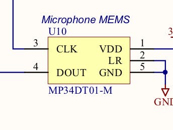
HardwareThe two microphones are connected to two pins of the MCU, one for the clock (that we have to provide to them), and one for the output data. The two microphones are configured via their LR pin in stereo mode, so one microphone will provide a valid sample when the clock line is high, and the other when the clock is low.
From the same datasheet, we can also find the pins that the microphones are connected to:
The signal that we receive from the microphones is in Pulse Density Modulation (PDM) format, a digital format that encodes the analog audio amplitude as the average density of high pulses in its bitstream.
A PDM signal can be converted into a Pulse Code Modulation (PCM) signal by averaging the received bits in a sliding window, so that the correct amplitude is recovered. After decoding, a PCM signal is composed of a series of multi-bit samples, representing the signal amplitude over time.
For more information on PDM and PCM signals, see this document.
The DFSDMThe two microphone pins, as their alternate function #6, can be connected to a peripheral inside the MCU called Digital filter for sigma delta modulators, or DFSDM for short. It's a pretty complex peripheral which can be configured in a number of ways (see RM0351, chapter 24) and one of its uses is exactly the one we need, decoding and processing PDM signals.
Overall, it can be divided into the following:
- Audio clock generation
- 8 serial transceivers for serial data input
- 8 alternative input units for parallel data input
- 4 filter and integrator units
- Various units for failure monitoring
For this project, we will use the clock generation circuitry, serial transceiver 2 and filter unit 0.
Clock generationThe first step to get any output out of the microphone is to provide it with an audio clock. There are two options for the clock source: it can be derived from a clock coming out of the Serial Audio Interface peripheral, or it can be derived from the system clock directly. The former can be more precise and offers more flexibility, but the latter is simpler since there's one less peripheral to configure. Since this project only looks at the sound level and has no high quality audio requirements, I went with the second option.
The first thing to do is to enable the DFSDM clock, or otherwise the peripheral will be kept in shutdown. The audio clock source is then configured in the CHCFGR1 register of the first transceiver:
static void set_ckout_freq(uint32_t target_hz) {
    uint32_t bus_clock = periph_apb_clk(APB2);
    uint32_t div = bus_clock / target_hz - 1;
    div &= 0xFF; // 8 bit divisor
    ch(0)->CHCFGR1 |= div << DFSDM_CHCFGR1_CKOUTDIV_Pos;
}

void audio_init(gpio_t ckout, gpio_t datin, audio_cb_t cb) {
    // First of all, initialize the pins
    gpio_init(ckout, GPIO_OUT);
    gpio_init_af(ckout, GPIO_AF6);
    gpio_init(datin, GPIO_IN);
    gpio_init_af(datin, GPIO_AF6);

    // Enable the DFSDM clock
    periph_clk_en(APB2, RCC_APB2ENR_DFSDM1EN);
    ch(0)->CHCFGR1 = 0;

    // Initialize the CKOUT audio clock signal to 1MHz
    set_ckout_freq(1000000);

[...]
(The code examples are all taken from audio.c, where the full source code can be found)
After this step, the microphones will start to produce PDM data, so the rest of this article shows how to decode and use it.
Input transceiverFrom the board schematic, we can see that the microphones are connected to the DATIN2 pin, which is the input of transceiver 2. So the next step is to initialize it and tell it where the clock is coming from
ch(2)->CHCFGR1 |= DFSDM_CHCFGR1_SPICKSEL_0; // clock from CKOUT
ch(2)->CHCFGR1 |= DFSDM_CHCFGR1_CHEN; // enable ch2Once the signal is deserialized, it goes through a filter. The transceiver -> filter connection is pretty flexible, so I chose filter 0, for no special reason.
The filtering unit is subdivided into two parts, the filter itself and an integrator unit, which can be used to accumulate consecutive samples before processing. The filter order can be configured, and an oversampling factor can be set on it for additional smoothing of the signal. In this project, the configuration is as follows:
- 4th order filter, with 23x oversampling
- No integration (integration oversampling ratio set to 1)
Or, in code:
flt(0)->FLTCR1 |= 2 << DFSDM_FLTCR1_RCH_Pos; // filter 0 reads channel 2
flt(0)->FLTCR1 |= DFSDM_FLTCR1_RCONT; // continuous conversion
flt(0)->FLTCR2 |= DFSDM_FLTCR2_REOCIE; // end of regular conversion interrupt enable
flt(0)->FLTFCR |= 4 << DFSDM_FLTFCR_FORD_Pos; // Filter order
flt(0)->FLTFCR |= 22 << DFSDM_FLTFCR_FOSR_Pos; // Filter oversampling ratio
flt(0)->FLTFCR |= 0 << DFSDM_FLTFCR_IOSR_Pos; // Integrator oversampling ratio
flt(0)->FLTCR1 |= DFSDM_FLTCR1_DFEN; // enable flt0
As a result of the oversampling, from the original 1MHz audio clock we get a 1MHz/23 = ~43.4KHz audio signal, a frequency that is close enough to one of the standard audio frequencies, 44.1KHz, for this application.
Enabling the DFSDMAs a final step, the peripheral has to be enabled, its interrupt signal has to be unmasked and the conversion started:
ch(0)->CHCFGR1 |= DFSDM_CHCFGR1_DFSDMEN; // Enable DFSDM
NVIC_EnableIRQ(DFSDM1_FLT0_IRQn);

flt(0)->FLTCR1 |= DFSDM_FLTCR1_RSWSTART; // start conversionThe peripheral offers two ways to output its data: it can fire an interrupt whenever data is ready, or it can store the data in RAM via DMA. For this project, I chose the simpler first option, so our ISR will be called whenever a new audio sample is ready
The ISR applies an additional single pole low pass filter in software, and periodically takes the resulting value, converts it to dB, and then passes it to the main logic, which can decide whether to trigger the alarm.
static double y = 0, y_old = 0;
static double alpha = 0.001;
void isr_dfsdm1_flt0(void)
{
    uint32_t data = flt(0)->FLTRDATAR >> DFSDM_FLTRDATAR_RDATA_Pos;
    // Single pole low pass filter
    double x = (double)data;
    y = alpha * x + (1.0 - alpha) * y_old;
    y_old = y;
    if(++num_samples == SAMPLES_PER_MEASURE)
    {
        double db = 20.0 * log10(y) - 26.0;
        audio_cb(db);
        num_samples = 0;
    }
}At least for this project, this is the full audio processing pipeline required. The DFSDM is a lot more powerful than what shown here, and the MCU offers hardware acceleration for signal processing functions such as the Fourier transform, which can be used in more advanced processing. For example, if we wanted to filter out some frequencies to only trigger when sound in the human voice frequency range is detected, we could do that with additional processing.


Comments