


Hardware components | ||||||
 |
| × | 1 | |||
 |
| × | 1 | |||
 |
| × | 1 | |||
Software apps and online services | ||||||
| ||||||
 |
| |||||
Why This Project?
This is a project on the AUP ZU3 (Zynq UltraScale+ ZU3EG) as part of research on the AUP-ZU3 board. Having already gotten my feet wet with the board, I wanted to go deeper by building a full PetaLinux image from scratch, getting Linux to boot from an SD card, and demonstrating that the PS can communicate with hardware on the PL side via the AXI GPIO peripheral.
How It Works
The Zynq UltraScale+ has two sides: the Processing System (PS), which runs Linux on ARM Cortex-A53 cores, and the Programmable Logic (PL), which is the FPGA fabric. The two sides communicate over AXI buses.
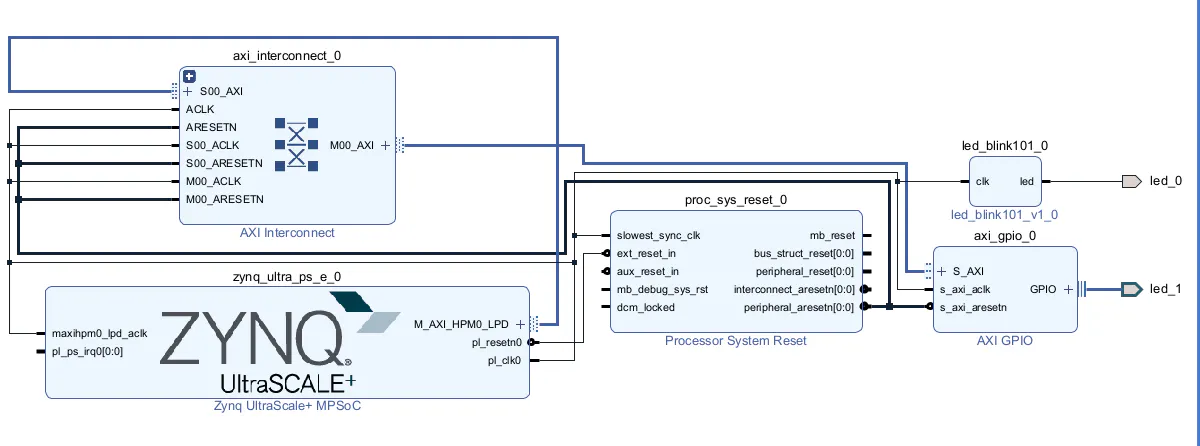
In Vivado 2022.1, I built a block design with:
- A custom LED blink IP core (led_blink101) for hardware-autonomous blinking
- An AXI GPIO peripheral (axi_gpio_0) mapped at address 0x80000000, connected to a physical LED constraint to AH2
The hardware design includes a custom LED blink IP core and an AXI GPIO peripheral. The PetaLinux image runs on the board's ARM Cortex-A53 processing system, communicates with the AXI GPIO over the AXI bus, and exposes it as a /sys/class/gpio device. This is the Xilinx-recommended approach for simple GPIO control from Linux user space
Follow these steps to begin with Ubuntu 20.04 installationStep 0 — WSL2 SetupPetaLinux requires a native Linux environment. We use WSL2 with Ubuntu 20.04 on Windows 11.
0.1 Enable WSL2Open PowerShell as Administrator:
wsl --install
wsl --set-default-version 2
0.2 Install Ubuntu 20.04wsl --install -d Ubuntu-20.04
0.3 Install Build Dependenciessudo apt install -y gcc g++ make git unzip python3 python3-pip \
libssl-dev libglib2.0-dev zlib1g-dev libncurses5-dev \
device-tree-compiler net-tools autoconf build-essential \
screen pax gawk curl wget vim nano
0.4 Configure Shell (Required by PetaLinux)sudo dpkg-reconfigure dash # Select No — use bash, not dash
echo "umask 022" >> ~/.bashrc && source ~/.bashrc
Petalinux installationStep 1 — Inspect the XSA Hardware DescriptionThe XSA file (exported from Vivado) describes the hardware — IPs, addresses, bitstream. Verify the AXI GPIO base address before building:
cp /mnt/e/Mo/design_1_wrapper.xsa ~/pet/
cd ~/pet && mkdir -p design_1_contents
unzip -o design_1_wrapper.xsa -d design_1_contents
grep -i "BASEADDRESS" ~/pet/design_1_contents/design_1.hwh | grep -i gpio
Expected: BASEADDRESS 0x80000000 — confirming axi_gpio_0 is mapped at that address.
Step 2 — Create PetaLinux ProjectSource the PetaLinux environment and create the project:
source ~/petalinux/2022.1/settings.sh
petalinux-create --t project --template zynqMP --name led_project
cd led_project
petalinux-config --get-hw-description=/mnt/e/Mo/design_1_wrapper.xsa
When the config menuconfig opens — Save and Exit. No changes needed here.
Step 3 — Configure Linux Kernelpetalinux-config -c kernel
In the kernel menuconfig, verify these are enabled (marked [=y]):
• GPIO_XILINX — Xilinx AXI GPIO driver
• GPIO_SYSFS — exposes GPIO pins under /sys/class/gpio
Both are enabled by default in PetaLinux 2022.1. Save and Exit.
Step 4 — Configure Root Filesystempetalinux-config -c rootfs
Navigate to Filesystem Packages → libs and enable:
• libgpiod
• libgpiod-dev
• libgpiod-tools
Under Image Features, enable:
• ssh-server-dropbear
• debug-tweaks (root login, no password)
• auto-login (automatic console login)
Save and Exit.
Step 5 — Configure Device Treepetalinux-config -c device-tree
Save and Exit immediately. Then manually edit system-user.dtsi to override the auto-generated GPIO direction settings:
edit
nano ~/led_project/led_project/project-spec/meta-user/recipes-bsp/device-tree/files/system-user.dtsi
Replace the file contents with:
/include/ "system-conf.dtsi"
/ {
};
&axi_gpio_0 {
xlnx, all-outputs = <0x1>;
xlnx, tri-default = <0x00000000>;
gpio-line-names = "led_1";
};
Why this matters: The auto-generated pl.dtsi sets xlnx, all-outputs = <0x0> and xlnx, tri-default = <0xFFFFFFFF>, which configures the GPIO as an input. Overriding to 0x1 and 0x00000000 forces it as an output so the LED can be driven.
Step 6 — Verify GPIO in Generated Device TreeAfter configuring, verify the GPIO node appears correctly in the workspace:
find ~/led_project/led_project/components/plnx_workspace -name "*.dts" -o -name "*.dtsi" 2>/dev/null \
| xargs grep -i gpio 2>/dev/null | grep -i "axi_gpio|gpio@8"
cat ~/led_project/led_project/components/plnx_workspace/device-tree/device-tree/pl.dtsi \
| grep -A 20 "gpio@80000000"
Step 7 — Buildpetalinux-build
First build takes approximately 30–60 minutes. The build system compiles the kernel, device tree, rootfs, and generates the FIT image. Subsequent builds with small changes are much faster.
Step 8 — Verify Boot Filesls -lh ~/led_project/led_project/images/linux/
Verify the GPIO node made it into the compiled DTB:
sudo apt install -y device-tree-compiler
dtc -I dtb -O dts ~/led_project/led_project/images/linux/system.dtb 2>/dev/null | grep -A 25 "gpio@80000000" | head -30
Step 9 — Package and Copy to SD Cardpetalinux-package --boot --fsbl --fpga --u-boot --force
cp ~/led_project/led_project/images/linux/BOOT.BIN /mnt/e/Mo/mo/
cp ~/led_project/led_project/images/linux/image.ub /mnt/e/Mo/mo/
Copy both files to the root of a FAT32-formatted SD card. The SD Card Formatter tool was used to prepare the card.
Step 10 — Create Auto-Boot ScriptBy default U-Boot attempts PXE network boot and hangs with "No ethernet found". A boot script tells it to load from the SD card instead:
cd ~/led_project/led_project
cat > boot.scr.txt << 'EOF'
fatload mmc 0 0x10000000 image.ub
bootm 0x10000000
EOF
mkimage -A arm -T script -C none -n "Boot Script" -d boot.scr.txt boot.scr
cp boot.scr /mnt/e/Mo/mo/
SD card should now have three files:
• BOOT.BIN — FSBL + PMU + ATF + U-Boot + Bitstream
• image.ub — Kernel + Device Tree + Rootfs
• boot.scr — Auto-boot script
Step 11 — Boot the ZU3 Board• Insert the SD card into the AUP ZU3
• Open PuTTY: Serial, select your COM port, 115200 baud, 8N1, No flow control
• Power on the board
• U-Boot loads automatically and boots Linux
If auto-boot does not trigger, type the following at the U-Boot prompt:
fatload mmc 0 0x10000000 image.ub
bootm 0x10000000
Step 12 — Control the LED from LinuxOnce Linux boots, login (root, no password with debug-tweaks), then:
Identify the GPIO chipls /sys/class/gpio
cat /sys/class/gpio/gpiochip507/label
# Expected: 80000000.gpio
Control via sysfsecho 507 > /sys/class/gpio/export
echo out > /sys/class/gpio/gpio507/direction
echo 1 > /sys/class/gpio/gpio507/value # LED ON
echo 0 > /sys/class/gpio/gpio507/value # LED OFF
Or use the LED control scriptcd /home/root
./led_control.sh on
./led_control.sh off
./led_control.sh blink
Demo: Full video demonstration of PetaLinux booting and LED control is available as petlinix_demo.MOV — attach to the Hackster project's Video section.
ConclusionThis project demonstrates a complete FPGA embedded Linux development flow on the AMD/Xilinx Zynq UltraScale+ AUP ZU3 — from Vivado hardware design and XSA export through PetaLinux build, SD card boot, and Linux user-space LED control via sysfs GPIO.
Key takeaways:
• PetaLinux 2022.1 on WSL2/Ubuntu 20.04 is a viable and stable host setup
• Device tree customization (system-user.dtsi) is essential for correct GPIO direction
• The sysfs GPIO interface requires no kernel driver — just echo commands from user space
• boot.scr eliminates U-Boot PXE boot failures on boards without Ethernet
• This foundation enables more advanced work: DPU inference, camera pipelines, V2X communication


Comments