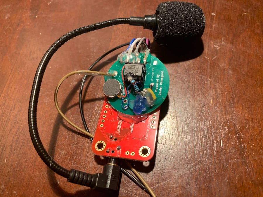
Sleep Apnea threatens the lives and proper respiratory function of up to 20% of the global population, says The National Sleep Foundation, and 85% affected don't realize they have it. In the image above, what looks like a mess of hot-glue is a device that tracks, records, and alerts users to instances of potential apnea via audio, visual, and vibrational systems.
Step One: The Components
Since I had hoped to make this device as concealed and small as possible since users would have to sleep near it, I knew the standard Arduino Uno wouldn't work, as it usually doesn't work for prototypes, and the ATmega328 wouldn't be ideal because of its size. To these ends, my project incorporates the ATtiny85. Don't be fooled. This IC packs a powerful punch, with ADC peripherals, PWM, eight pins, many of which I/O, and its size. Consequently, it's perfect for small projects like SADD.
Step Two: Speech Recognition
Furthermore, I also needed a programmable voice recognition module. The Elechouse v3.1 Voice Recognition Module was perfect for this application. It loads up to seven unique speech patterns. This single advantage is why my project is so useful. Users can record their sleep sounds of actual apnea and program their audio recordings of their Sleep Apnea right into the module, making it unique to each user and that much more accurate.
Step Three: Bringing It Together
When any one of the seven snore or abnormal breathing patterns are sensed by the module, a vibration motor is activated, in an attempt to alert the user and wake them up to get them out of their Sleep-Apnea episode. The blue LED takes a special voice command: system_check. System check takes a tally of every time the device was used throughout one's night. The LED flashes for every incident of Sleep Apnea the user had throughout the night. Since the voice commands last for 1.5 seconds, multiplying the number of flashes by 1.5 yields an estimate of how long one experienced abnormal snoring and or shortness of breath. This counter resets when power is switched on and off or when the user speaks the system_check voice command.
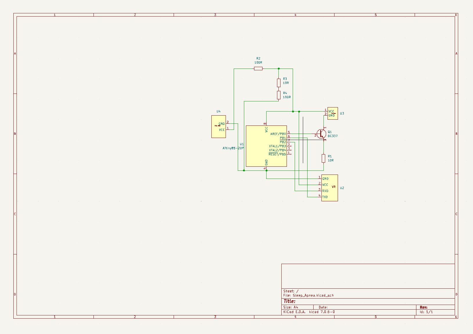
Step Four: The Circuit Board
The circuit board isn't exactly how everything ended up being soldered on, hence the messiness. In addition to changing certain pins around, I had to get rid of the voltage divider and parts of the transistor circuit. Overall, this is a semi-accurate model of my circuit board. The idea is that it connects all the components together to the IC and makes the device miniature.
Step Five: The Code
If you would like to train your custom voice commands, follow the instructions on the Elechouse v3 Voice Recognition Module datasheet: it's pretty simple. After training them onto the module, replace my seven instances of voice commands with your custom sigs - signal phrases. You must also go into the library that comes with the VR module and change all of the instances of "Serial" to "mySerial" inside the.h file and paste the line of code "SoftwareSerial mySerial(1, 0);" inside of the.cpp file inside the library. These steps are necessary because the ATtiny85 doesn't have a built-in UART, the hardware that makes serial communication possible. You must use serial comms via software. You can edit these files by opening them inside a text editor like VS Code.
Step Six: Soldering
There are a few minor adjustments to the circuit-board file seen above. The first thing you want to do is solder an LED and a resistor in series with D3 and GND. Next, short the resistor space at the bottom of the circuit board. Additionally, short RX of the VR module to D1 and TX of the VR module to D0. Finally, the third pad on the right needs to be connected to the vibration motor. Short the other end of it to GND.
Step Seven: Going Further
SADD is only a prototype and has some issues with accuracy and consistency. Not every first iteration is perfect. However, I intend to make it better and more consistent in the future. For now, check out my personal website for projects like the one you see above.


Comments