Refuse to pay for a large, overpriced, boring old time-responsive alarm clock? Create your own that is tiny, cheap, and responds to light, not time. The alarm utilizes a voltage divider whose Vout changes with light intensity.
Step One: The Components
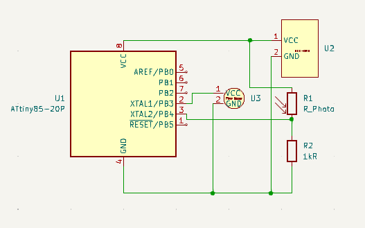
The image above showcases a photo resistor, a resistor whose value changes with light exposure and intensity. Couple this with a 1k resistor, and you have a voltage divider with a readable Vout, perfect for a light alarm. The component that actually makes the sound is the piezo buzzer. I am simply beeping it on repeat, but if you would like, you could program it to wake you up to some Star-Wars theme songs, or any other song or note for that matter. Many libraries have created sketches that use the piezo buzzer to produce popular songs. They're a google search away. Finally, I used the ATtiny85 due to its small size.
Step Two: The Circuit Board
With a width of only 17mm, this alarm clock is quite miniature and cheap. The circuit board in general just connects each component to the ATtiny85 and to the power input and output. I designed it using KiCad. Check out my profile for a tutorial.
Step Three: The Code
The code is super adjustable and simple. If you would like to buzz the sound more often, shorten the time delay. And if you would like to code certain sounds, notes, tones, or songs, there are libraries for using the piezo buzzer on the ATtiny85. The sounds are very customizable. I simply used a digital HIGH value to keep it simple and wake me up, even though this voltage value creates a slightly annoying sound. Nonetheless, it's quite loud and does the trick.
Step Four: Soldering
Since the circuit board is small and there are delicate components used, the order in which you solder components matters. I would recommend soldering the power connections, 5V and GND, first, followed by the ATtiny85, resistor, photo resistor, and finally, the piezo buzzer. Be careful not to heat up the board too much, as the excess energy will damage the board and or components. Also, before plugging in power, make sure to test for continuity when you are finished soldering all of the components.
Step Five: Going Further
After building the ATtiny85 Light Alarm, check out my personal website for projects like the one you see above.


Comments