This temperature and fire alarm alerts users of instances of extreme heat and or a dangerous fire near or around the device. Read below how it it works and why you need it in your home.
Step One: The Components
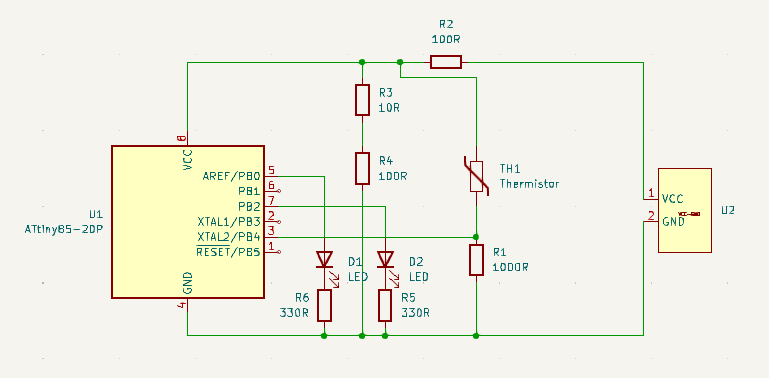
The image above is what's known as a thermistor, a temperature-dependent resistor. Without this component, my project doesn't work. As temperature changes, the conductivity of the component changes. This effect changes the resistance of the component. But how does the ATtiny85 use this information? It can't read resistances directly. Combining this component with a 1k resistor, we get a voltage divider, a topology that has a calculated Vout as a function of the resistance around the node. To these ends, as the resistance changes, Vout changes and can be read by the ATtiny85.
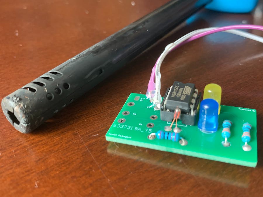
Step Two: The Circuit Board
With a width of only 21mm, this printed circuit board is tiny. It isn't an exact replica to my actual project because after fabrication, I realized the voltage-divider power circuit was not needed. Nonetheless, the rest of the board functions as intended.
Step Three: The Code
The code is super adjustable and simple. If you would like to blink one or both of the LEDs faster, shorten the time delay. The LEDs are very customizable. I simply used a digital HIGH value to light up the LEDs and a digital LOW to turn them off. Doing this repeatedly creates the blinking. You may also change the temperature ranges by adjusting the conditional statements.
Step Four: Soldering
Since the circuit board is small and there are delicate components used, the order in which you solder components matters. I would recommend soldering the power connections, 5V and GND, first, followed by the ATtiny85, resistors, LEDs, and finally, the thermistor. Be careful not to heat up the board too much, as the excess energy will damage the board and or the components. Also, before plugging in power, make sure to test for continuity when you are finished soldering all of the components. The only changes from the original circuit board is shorting a 5V power supply to the VCC node and shorting a GND power supply to the GND node on the board.
Step Five: Going Further
After building the ATtiny85 Temperature and Fire Alarm, check out my personal website for projects like the one you see above.


Comments