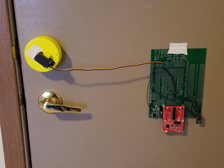
Daniel Hill
Published

WiFi Controlled Door Lock

Lock and unlock your door from your phone using WiFi.

IntermediateShowcase (no instructions)2,195
WiFi Controlled Door Lock

Things used in this project

Hardware components

MSP-EXP430G2ET Value Line MSP430 LaunchPad™ Development Kit
Texas Instruments MSP-EXP430G2ET Value Line MSP430 LaunchPad™ Development Kit
×1
Custom PCB
Custom PCB
×1
HS-311 Standard Servo
×1
ESP8266 ESP-01
Espressif ESP8266 ESP-01
×1
6V Power Supply
×1
LED (generic)
LED (generic)
×3
Jumper wires (generic)
×1
Resistor 220 ohm
Resistor 220 ohm
×1
5 Volt Regulator
×1
3.3 Volt Regulator
×1
Capacitor 10 µF
Capacitor 10 µF
×4
Fixed Network Resistor, 1.5 kohm
×1
Fixed Network Resistor, 470 ohm
×1

Software apps and online services

TCP Server

Hand tools and fabrication machines

3D Printer (generic)

Story

Read more

Custom parts and enclosures

Door Lock Mount Drawing

Inventor Drawing pdf of mount on door lock. Note that the RC Servo rotating actuator is not centered to the part. My door lock was a few fractions of an inch below the absolute center of the circle mount.

Schematics

Wiring Schematic

Wiring Schematic to connect ESP8266 to MSP430 to RC Servo.
Note: This does not include the power supply schematic for the MPS430, nor does it show how to convert the 6V Power Supply to 3.3V.

Code

user_Project.c

C/C++
Code used to run ESP8266 through MSP430. Please read comments in Timer_A function as the code needs to be uploaded a few times. The timecheck intervals are arbitrary as long as there is sufficient time between commands for the entire queue to be delivered.
There is absolutely a better way to write this code.
#include "msp430g2553.h"
#include "UART.h"

void print_every(int rate);

char newprint = 0;
long NumOn = 0;
long NumOff = 0;
int statevar = 1;
int timecheck = 0;

char stringsent[10]={0,0,0,0,0,0,0,0,0,0};//initializes a send array to see if messages are sending correctly.. I didnt use this much because i can also see this in the receive string
int stringcount=0;//stringsent indexer

char stringrec[150]; //array to receive messages so i can see what's being received
int reccount=0; //string receive indexer

char recString=0;//string to receive RXBuffer

char message=0; //message received over TCP
char message_prev=0; //previous message received over TCP
int TCPFlag=0; //set TCP flag to hold next received value

int  TCPCompare=0;//COmpare varibable to make sure that TCP Encodings are correct
char TCPEnc1[9]={43,73,80,68,44,48,44,50,58}; //This is the string that precedes a TCP Value send by the TCP CLient app
char TCPEnc2[9]={43,73,80,68,44,50,44,51,58}; //String that precedes a TCP Value form the TCP Server app.. I have no idea why the two are different and didn't end up looking into it

int sendflag=0; //Flag to show if door has been unlocked (1) or locked (2) or no message (0)

void main(void) {

;    WDTCTL = WDTPW + WDTHOLD;                 // Stop WDT

    if (CALBC1_16MHZ ==0xFF || CALDCO_16MHZ == 0xFF) while(1);

    DCOCTL = CALDCO_16MHZ;    // Set uC to run at approximately 16 Mhz
    BCSCTL1 = CALBC1_16MHZ;

    // Initialize Port 1
    P1DIR  = 0x10;//Setup pin 4 as an output
    P1OUT = 0x00;//initialize as 0
    P1SEL = BIT1+BIT2;//set bits 1 and 2 to allow for uart communication
    P1SEL2 = BIT1+BIT2; //set bits 1 and 2 to allow for uart communication

    // Timer A Config
    TACCTL0 = CCIE;             // Enable Periodic interrupt
    TACCR0 = 16000;                // period = 1ms
    TACTL = TASSEL_2 + MC_1; // source SMCLK, up mode

    // Initialize Port 2 for Servos
    P2DIR |= 0x12; //Step 1 of setting P2.1 to TA1.1 and P2.4 to TA1.2
    P2SEL |= 0x12; //Step 2 of setting P2.1 to TA1.1 and P2.4 to TA1.2
    P2SEL2 &=~ 0x12;//Step 3 of setting P2.1 to TA1.1 and P2.4 to TA1.2
    TA1CCR0=40000;//Sets the period to 20ms
    TA1CCTL1 = OUTMOD_7; //PWM Output mode 7
    TA1CCTL2 = OUTMOD_7; //PWM Output mode 7
    TA1CTL=TASSEL_2+MC_1+ID_3;//SMCLK, Up Mode to CCR0, clock divider =8.
    //period is set to 20ms by 20ms=40000/(16,000,000/8)

    Init_UART(115200,1);    // Initialize UART for 115200 baud serial communication

    _BIS_SR(GIE);       // Enable global interrupt

}

// Timer A0 interrupt service routine
#pragma vector=TIMER0_A0_VECTOR
__interrupt void Timer_A (void)
{
    timecheck++; // Keep track of time for main while loop.
    print_every(500);  // units determined by the rate Timer_A ISR is called, print every "rate" calls to this function

    //Factory Resets, loses autoconnect, do this if changing wifi connection or if something got messed up and saved in flash
//    if (timecheck==1){
//        UART_printf("AT+RESTORE\r\n");
//    }

//  Connects Wifi
    //Saved in Flash is using _DEF, use _CUR to have only for the current run
    //THis only needs to be set once.
    //The time delays are insignificant.... just make sure that all of the data is being send and that each command ends with \r\n
//    if (timecheck==1250){
//        UART_printf("AT+CWMODE_DEF=1\r\n"); //Sets station mode (=1) in flash
//    }
//    else if (timecheck==1300){
//        UART_printf("AT+CWJAP_DEF=\""); //Saves WIFI connection in flash
//    }
//    else if (timecheck==1350){
//        UART_printf("SSID\",\"");//Replace SSID With your wifi network
//    }
//    else if (timecheck==1400){
//        UART_printf("Password\"\r\n");//Replace Password with your wifi password
//    }
      //This should reply something like "wifi connected"


//    //Sets ESP as TCP Server
    //this needs to be done every time.
    if (timecheck==3000){
        UART_printf("AT+CIPMUX=1\r\n");//multiple connection enabled (=1)
    }
    else if (timecheck==3250){
        UART_printf("AT+CIPSERVER=1,1500\r\n");//creates server for first connection at port 1500.
    }
    else if (timecheck==3500){
        UART_printf("AT+CIFSR\r\n");//reads out ip and mac of     the server. something like 192.168.4.1 for ip
    }
    else if (timecheck==4000){
        UART_printf("AT+CIPSTART=2,\"TCP\",\"192.");//begins a tcp connection in the second connection, also at port 1500.  The IP Address here is my phone.. and thi sis the ip at my house
    }                                               // At the lab it was a different, for obvious reasons
    else if (timecheck==4100){
        UART_printf("168.0.3\",1500\r\n");
    }
    if ((timecheck%500)==0){//Don't want to check if a message needs to be send every second, otherwise this could overload our tcp connection
        if (sendflag==1){//if the sendflag =1, that means the door has been unlocked
            UART_printf("Unlocked\n");//send message to unlock door.  Sending messages is a very weird protocol that I will talk about with the CIPSEND COmmand
            sendflag=0;//reset the send flag
        }
        if (sendflag==2){//if the sendflag=2, door has been locked
            UART_printf("Locked\n");//up
            sendflag=0;//resets send flag
        }
    }

    if (message==message_prev){ //if there is not a new messgage
        //do nothing
    }
    else{// if there IS  new message
        switch (message){
        case  48://if the message is ascii 48 (0), we want to unlock the door
            P1OUT &= ~0x10;//turn off the led indicator
            TA1CCR2=1200;//set the servo position to the unlocked position
            sendflag=1;//set the send flag up to be print unlocked
            UART_printf("AT+CIPSEND=2,9\r\n");//okay, so here, we use the cipsend command.. the 2 is for the connection we want to send to (to my phone, as mentioned above, is 2)
                                              // the next is the length of our send.. above, I use "Unlocked\n" for this case.  this is 9 characters because of the newline
                                              //right after this command, the next thing to be sent is the message.  the CIPSEND command will send each character of the message until the length (9)
                                              // has been reeached, all of the online forums said not to follow your message with a carriage return (\r) so I did not...
                                              //This could get troublesome using the awful layout that I have, where the message isn't even in the same iteration.
                                              //So using this, it's best to wait unitl all of the other things are setup and we have no queued AT Commands to send
                                              //Basically, to use this command, do: at+cipsend,<connection#>,<data length>\r\n then "messsage of <data length> characters"
            break;
        case 49://ascii49 (1), want to lock the door
            P1OUT |=0x10;//turn on the led indicator
            TA1CCR2=3500;//set servo position tot he locked position
            sendflag=2;//send flag to print locked
            UART_printf("AT+CIPSEND=2,7\r\n");//send a message of 7 characters (locked\n);
            break;
        }
        message_prev=message;//set message_prev to message so we are not triggered until adifferent message comes
    }


}

// USCI Transmit ISR - Called when TXBUF is empty (ready to accept another character)
#pragma vector=USCIAB0TX_VECTOR
__interrupt void USCI0TX_ISR(void) {

    if(IFG2&UCA0TXIFG) {        // USCI_A0 requested TX interrupt

        if (stringcount<10){
            stringsent[stringcount]=UCA0TXBUF;
            stringcount++;
        }

        if(printf_flag) {
            if (currentindex == txcount) {
                senddone = 1;
                printf_flag = 0;
                IFG2 &= ~UCA0TXIFG;
            } else {
                UCA0TXBUF = printbuff[currentindex];
                currentindex++;
            }
        } else if(UART_flag) {
            if(!donesending) {
                UCA0TXBUF = txbuff[txindex];
                if(txbuff[txindex] == 255) {
                    donesending = 1;
                    txindex = 0;
                }
                else txindex++;
            }
        } else {  // interrupt after sendchar call so just set senddone flag since only one char is sent
            senddone = 1;
        }

        IFG2 &= ~UCA0TXIFG;
    }

}


// USCI Receive ISR - Called when shift register has been transferred to RXBUF
// Indicates completion of TX/RX operation
#pragma vector=USCIAB0RX_VECTOR
__interrupt void USCI0RX_ISR(void) {


    if(IFG2&UCA0RXIFG) {  // USCI_A0 requested RX interrupt (UCA0RXBUF is full)

        recString=UCA0RXBUF; //reads the RX Buffer and clears it

        //This is definitely not the best way to do this... but hey, it works! Please don't judge me :))

        if (TCPFlag==1) {//checks if TCP Received flag is set by previous values received (+IPD.....)
            message=recString;//takes next charaacter after flag
            TCPFlag=0;//resets flag
        }
        if (reccount<150){//Just indexing a long, long list so i can see what's being returned by the ESP8266
            stringrec[reccount]=recString;//adding character by character the string
            int i=0;//for loop variable

            for (i=-8;i<1;i++){// take the previous 9 characters received by the RXBuffer to check if its a message over TCP
                if ((stringrec[reccount+i]==TCPEnc1[i+8])){//if in the first TCP encoding,
                    TCPCompare++;//increase the TCP COmpare flag
                }
                else if ((stringrec[reccount+i]==TCPEnc2[i+8])){//if in the second TCP encoding
                    TCPCompare++;//increase the TCP COmpare flag
                }
            }
            if (TCPCompare==9){//If the flag is up to 9 (full), then make the TCP Flag=1
                TCPFlag=1;
            }
            TCPCompare=0;//reset the TCPCOmpare counter to 0
            reccount++;//increase the reccount variable to index the array
        }
        else{
            reccount=0; //if reccount greater than 150, reset the reccount variable to we can overwrite
        }

        IFG2 &= ~UCA0RXIFG;
    }

}

Credits

Daniel Hill

Daniel Hill

1 project • 2 followers
Thanks to Dan Block.

Comments