

Hardware components | ||||||
 |
| × | 1 | |||
 |
| × | 1 | |||
 |
| × | 1 | |||
 |
| × | 1 | |||
 |
| × | 1 | |||
 |
| × | 1 | |||
| × | 1 | ||||
 |
| × | 1 | |||
Software apps and online services | ||||||
 |
| |||||
Hand tools and fabrication machines | ||||||
 |
| |||||
 |
| |||||
 |
| |||||
New Facts from WHO reveal that COVID-19 actually spreads via airbourne. Recently, this virus can "hanging" for 20 minutes on the air, sticking to the micro-droplets of invected breath. "Scary" that is the word comes to my mind. When it comes to this situation, one of effective solution is mind your distance.
The aim of this project is creating a device that will help you to check your distance to another person. This device using RSSI (received signal strength indicator) as the main feature for distance detection. When you break the save distance, in this project is set at 3 Meters, this Device will give a warning signal by beeping a buzzer.
In order to reduce your interaction with your houses front door, this device also can be used as your main key by using a wifi. With registered MAC address in the wifi AP, this device will recognize you, and tell the automatic door opener to do its job.
Unfortunately, this project is not built on Arduino MKR 1010, So maybe the code won't work on it. But you can implement the theories, diagram, or steps to build your own version using MKR1010.
THEORIESA bit mathematics won't hurt, I think. The calculation of RSSI is described in equation[1]. You can read this paper[1] if you want more detailed informations. The paper is actually talking about BLE positioning system, but we won't go that far, one thing we need is this simple equation.
RSSI is the signal strength.
A is RF Parameters, defined as the absolute energy which is represent by dBm at a distance of 1 meter from the transmitter,
n is the signal transmission constant, and it is relevant to signal transmission environment;
d is the distance from the transmitter node to the receiver node [1].
If you read the paper, there is method to calculate signal transmission constant/ environment constant. Actually I am not the person who do love mathematics, I hope I am not the only one :), so I just skipped this one.
###RF Parameters and Environtment Constants ###
I did some experiment to acquire RF Parameters and Environment Constant (A and n) by measure the d and RSSI. The distance at 1 meters gives RSSI value at -62, at 5.5 meters gives RSSI value -93 and half meters at -57.
Then I calculated the RSSI manually using formula 1 with a certain constant value. I got:
Well I think we found the Constants. Maybe German's Engineer would not agree & laughing at this method, because they always stick to the mathematics :). And to avoid a debate, you are free to calculate the value of A and n by your way, and change it in the code.
REBUILD PROJECT
In order to rebuild the project, it needs to collect all the hardware and software as mentioned above. At least it needs 2 ESP 32, 1 ESP 8266, 1 enclosure, SMD components, Soldering tools, and Arduino IDE. It is not difficult to rebuild it, it needs couple hours to joint all things together.if you didn't install arduino IDE on your computer, You need to download newest one from official Arduino website
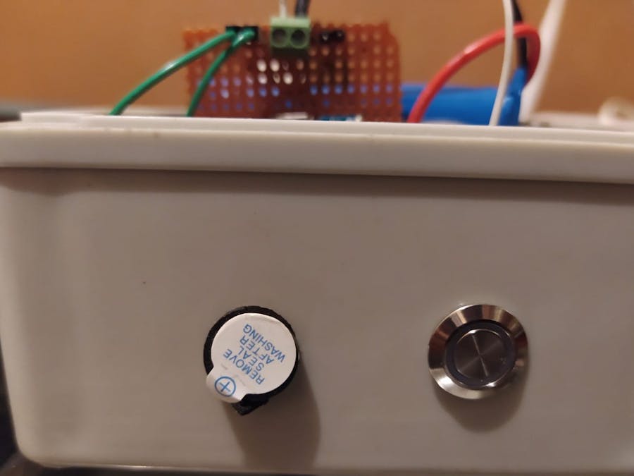
A. HARDWARE PREPARATION
The hardware for this project needs to be well prepared to avoid confusion at the process. Then you need to install ESP32 Board on Arduino IDE by following this article[2]. Try to load an example to make sure that esptool is installed properly. No need to solder all of the component, soldering is needed when it comes to assembly. There are some footages of my work:
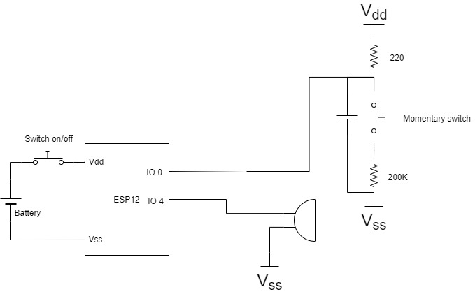
The PCB route will be explained in schematics.
B. SOCIAL DISTANCE MONITORING USING BLE
I am going to use flowchart to make it easier to comprehend. So, Lets take a look a flowchart below:
BLE Flowchart defines BLE working flow in this project. From this flowchart we will understand why we need at least 2 device of ESP12. One will act as broadcaster (In arduino IDE it is called BLE Server), and the others will act as Observer. Easy to understand :).
The BLE Broadcaster will Broadcast it's advertising data like UUID, UUID characteristics, Service, and (optional) a message. At the otherside, BLE Observer will scan all available BLE around. The result of scanned BLE will be BLE Name, Address, Service UUID, TX Power & RSSI.
To be able to gain RSSI information for Observer is by calling getRSSI() function in BLEAdvertisedDevice class in Arduino ESP BLE library, for example:
BLEAdvertisedDevice advertisedDevice;
Serial.print("RSSI: ");
Serial.println(advertisedDevice.getRSSI());
After device got RSSI, then we need to calculate the distance using equation above. Usually the hardware engineer will avoid a complicated mathematic calculation like LOG, also multiplication & division. Fortunately, the n value is constant, so the result of LOG(n) will always be a constant (LOG(n) = 0.72).
Since I don't know which device act as Obeserver or Broadcaster, I need a rule that will controll the mode of the device. This project using 10 seconds switching mode, means that the BLE will act as Broadcaster for 10 sec. then for next 10 sec, the device will change its mode to Observer mode. Device will act as BLE Observer/Broadcaster as long as there is no interrupt from user.
C. TOUCHLESS DOOR UNLOCKER USING WIFI
NOTE:Activating wifi+BLE at same time will cause error in compilingand running. See Troubleshoot 1 and 2.
This Touchless door unlocker using wifi as the main feature, it needs at least 2 devices to do the job, they are ESP32 and ESP8266. ESP32 will act as client, otherwise ESP8266 will act as access point. So, the touchless door is divide into 2 parts, Station(client) and Access Point.
###### CLIENT ############
The workflow is simple and easy to understand, described in flowchart below:
As mentioned earlier, the wifi will active if there is GPIO interrupt happens, then it will rise a flag to inform the loop function that a button has been pressed. The flag will be cleared and the device will doing the job, it's opening the door. To open the door, Client needs to connected to wifi AP. In this case, clients need to know SSID and password. We need to pay attention to the flow. It will create a infinite loop if the wifi not connected to the SSID. Which mean, this going to be a problem if the AP is crashing or lost its power. You can also put a timer or limited loop to avoid this problem.
As simple as that, then the next job is owned by AP to do the scan, detect and open the door.
##### Wifi AP ##########
After the client connected to AP, it is APs turn to do job, described in flowchart below:
First, the wifi needs to set to AP, then do some scanning. If there is a client connected to our AP, it will scan the IP and MAC also. As we can see from the code, the function that doing the trick is:
number_client= wifi_softap_get_station_num();
stat_info = wifi_softap_get_station_info();
This example provided in Ref[3] and Arduino example. wifi_softap_get_station_num() will scan the amount of connected client, wifi_softap_get_station_info() will print the client info, including IP and MAC addr.
Then our custom AP will match the registerd MAC with connected device, If there is a match, the door will be unlocked. It is double security :). First comes from SSID, second comes from registered MAC. This is also avoid your house being hijacked by intruder. If there is hacker (which is not a "hackster" :)) ), successfully bruteforce your SSID, they still can not unlock the door. Here the result of implementation:
The scope of this project is done here. It can be continued by creating customized door with DC motor or magnetic switch driven by ESP8266 GPIO.
D. TROUBLESHOOT
1. Error compile. Compiled file is exceed limit. This is solved by increasing yout default size of compiled file on board.txt. usually located in C:\Users\Name\AppData\Local\Arduino15\packages\esp32\hardware\esp32\1.0.4
2. Error running, something like this. rst:0x3 (SW_RESET), boot:0x13 (SPI_FAST_FLASH_BOOT). means you need to change ESP Partition scheme to "Huge App".[4]
D. DEMONSTRATIONS VIDEOS
Explanation: The test uses 1 broadcaster and 1 custom device. The broadcaster is always set as BLE broadcaster to avoid 2 device working as broadcasters. Then the custom device need to be separated to broadcaster. In this experiment, the custom device was brought away to 5-6 meters from broadcaster. The result shows that the device keeps beeping in range 3-4 meters and suddenly stop after 4-6 meters.
Explanation: The second test is used to measure devices senstivity test. from demo video, custom device was separated about 3 meters, then I took a small step backward & forward. The result is the device has a good sensitivity.
Explanation: Test 3 shows the result of door opener using wifi. The custom device succeed to open the door. As seen from demo video, it takes time (about 20 sec) for the custom AP to open the door for us. As I mentioned earlier in the diagram, The GPIO interrupt is used only to raise a flag, not running the door-opener function. This is the bottleneck of the system, if you try to run the door-opener function inside interrupt callback function, you will face a major problem. This is why, we need to tune the timing inside the loop to get the best action.
E. SPECIFICATIONS
- Battery: 4.7V 4000 mAh
- Power Consumption: Min: 15µA and Max: 400mA
- ESP12 & ESP8266
F. NOTES
>> Advantages:
- This device no need any additional range measurement sensor (example: ultrasonic sensor).
- has a good sensitivity
>> Disadvantages:
- Need at least two device to perform range detection, and one must act as broadcaster, the others act as observer.
- since the device is always running, there is small chance to implement a low power mechanism. This action may drain your battery in few hours (not yet measured for battery usage duration).
REFERENCES:
[1]. "Bluetooth positioning using RSSI and triangulation methods", Yapeng Wang, Xu Yang, Yutian Zhao, Yue Liu, L. Cuthbert, Queen Mary, University of London, 2013.
[2]. https://randomnerdtutorials.com/installing-the-esp32-board-in-arduino-ide-windows-instructions/
[3]. https://circuits4you.com/2018/01/31/esp8266-get-ip-mac-address-of-connected-devices/


Comments