

Hack a $35 Arduino-compatible nRF52 ARM Cortex activity tracker to build low power devices. Currently, used to prototype wearable medical devices at MATTER Lab. Complete tutorials and code for accelerometer gesture recognition, neural network training, and 3D model control using Bluetooth.
DetailsFor the past two years I have been using hacked nRF52832 activity trackers as a rapid prototyping platform for wearable devices. In fact, I use the exact activity tracker presented in this project for gesture recognition biofeedback and position tracking devices at the Child Mind Institute.
My goal is to present nRF52832 and nRF1822 activity trackers, in particular the X9 Pro, as a full fledged platform for prototyping low power devices.
Tutorials and Example Code:
- Blink, Button, OLED, Web Bluetooth (GATT Notifications) and Bluetooth Serial debugging Arduino example sketches that work with the X9 activity trackers (and most other activity trackers mentioned in this project with slight modification).
- Use of neural networks (LSTM MLP by way of synaptic.js) for gesture recognition using accelerometer data from the X9 streamed into a web browser over Web Bluetooth (HTML API).
- Adding additional GPIO the simple way
Neural Network Gesture Recognition with Web Bluetooth Tutorial
Stream sensor data from your hacked activity tracker into a web browser using the experimental HTML5 Web Bluetooth API. Sample data in different positions and train a neural network to distinguish position ie recognize gestures.
Got to the live site site HERE GitHub Repository for live site HERE
This is a GitHub site so all you have to do is fork the GitHub repository and you can create your own version of this site in seconds. Customize and hack it! (info on Web Bluetooth)
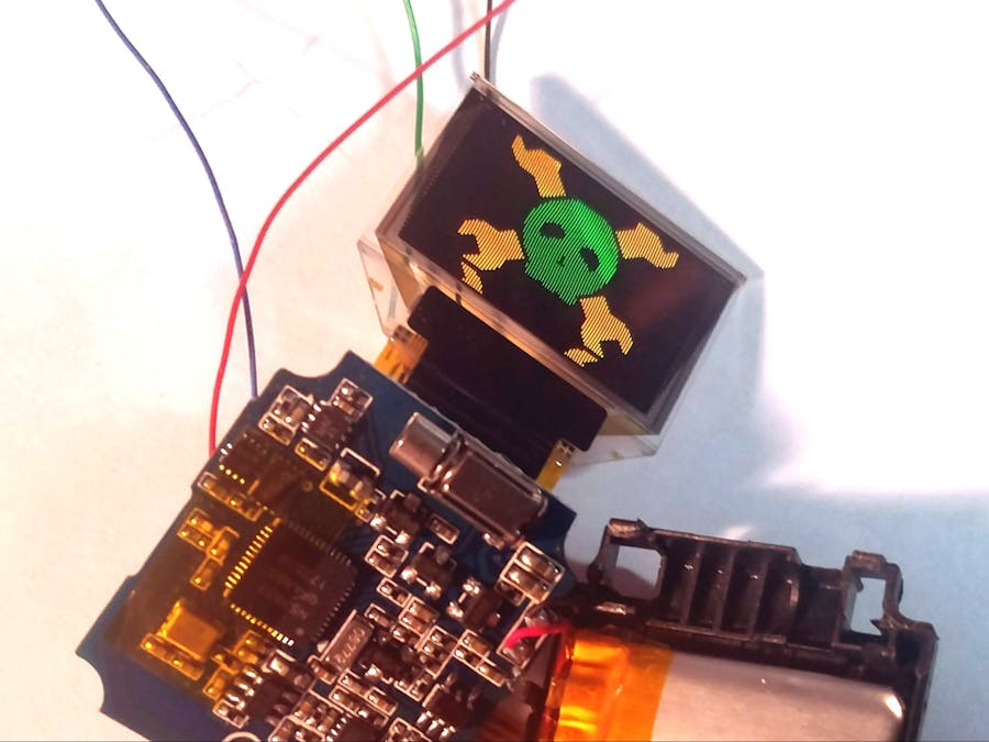
X9 Pro Activity Tracker Components
- nRF52832 ARM Cortex M4 SoC/MCU
- vibration motor
- 96x64 Color OLED display with SSD1331 controller IC
- Kionic KX126 Accelerometer with interrupt pin attached to MCU
- green LED for heart rate sensing
- photosensor for heart rate sensing
- 8MB SPI FLASH memory IC
- touch sense circuit
- COST: $35
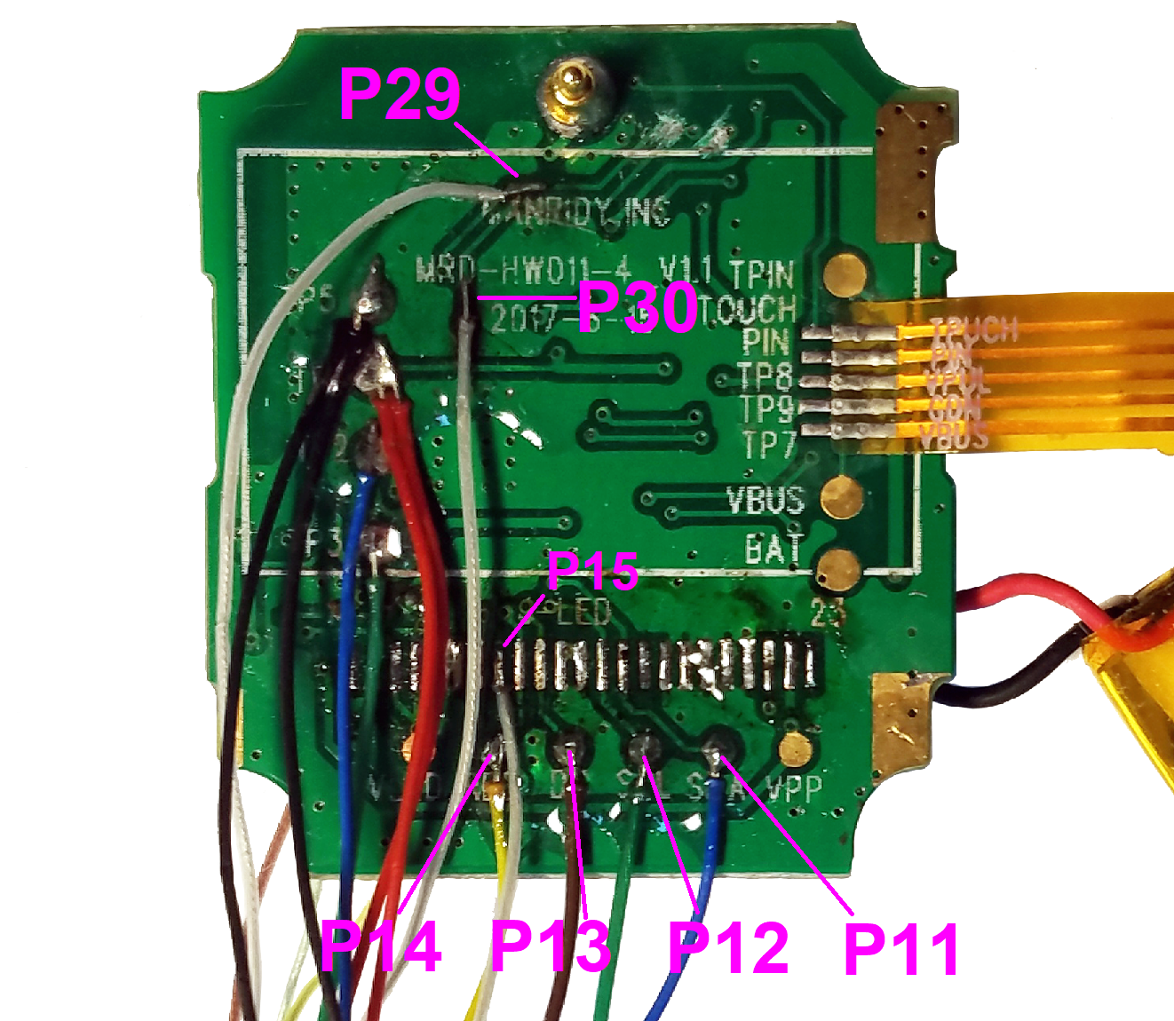
X9 Pro Activity Tracker MCU Pinout
- HR_LED_PIN 4
- HR_DETECTOR 29
- TOUCH_BUTTON 30
- VIBRATE_PIN 8
- BATTERY_PIN 28
- OLED_CS 15
- OLED_RES 14
- OLED_DC 13
- OLED_SCL 12
- OLED_SDA 11
- OLED_LED_POW 16
- OLED_IC_POW 17
- KX126_CS 24
- KX126_SDI 19
- KX126_SDO 20
- KX126_SCL 18
- KX126_INT 23
- FLASH_CS 22
- FLASH_SDI 19
- FLASH_SDO 20
- FLASH_SCL 18
... Read more »
Primary Project GitHub repo with code, documentati
Neural Network Web Bluetooth Demo
Lightsaber Web Bluetooth Demo
Heat Map Web Bluetooth Demo
3D Ball in Water Web Bluetooth Demo
Respiration Web Bluetooth Demo
Build instructionsStep 1
Aliexpress, Banggood, and Ebay are your best bet. Pricing will vary widely so it pays to look around.
LINK1LINK2LINK3LINK4LINK5LINK6
NOTE: I have purchased many X9 Pro activity trackers. Some of them have a green PCB and some have a blue one. It doesn't make a difference for the purposes of this tutorial. The traces on the PCB are arranged a little differently but all the components are the same.
Step 2
Use a hobby knife ("X-Acto" knife) to cut as much of the glue bonding the plastic cap to the metal body as possible. Getting a thin blade between the plastic and metal will gradually wedge the two apart. Take your time (I would budget at least 5 minutes) and work your knife all the way around the cap.
Step 3
Use a small screw driver or prying tool to carefully lift the plastic cap off the metal enclosure body. Take your time and work thy prying tool around the cap.
Separate the cap and put it aside for now.
Step 4
Unscrew the plastic retainer and put the screws somewhere you won't lose them.
Step 5
Carefully pry out the internal plastic enclosure.
Step 6
The PCB test pads that you need to solder are on the exposed side the the PCB, but all those cool chips are on the hidden reverse side. If you are like me you will definitely want to take a look. Carefully push back the plastic teeth retaining the PCB. You will see all the ICs in their glory and also the LiPo battery. Once you are done taking a peak put the main PCB back in the plastic internal enclosure.
Step 7
I always use flux. Flux dissolves accumulated oxidized metal from the top of the pads, making solder bonds easier and stronger.
Step 8
You may want to dab some glue on the solder point to reinforce it but that is strictly optional.
Step 9
Cut a groove in the plastic cap for the wires to fit through and reassemble the device just like you took it apart. Connect the wires to a bread board. Connect the Ground and Voltage Supply wires to a 3.3v bench power supply, as well as the ground and reference voltage connections from your SWD programmer.
Step 10
If you have not already installed the Arduino IDE, go ahead and do it. Then go to Sandeep Mistry's Nordic ArduinoCore GitHub repository (Arduino wrapper for the Nordic nRF5x SDK), download the ArduinoCore package and install on the Arduino IDE. There are excellent instructions in the GitHub repository README. Use the variant file for the X9 activity tracker found in the GitHub repository for this project.
Load the nrf52_X9Project_OLED sketch (attached to this project as a file) into the Arduino IDE. Make sure board is set to "Wearable nrf52 X9" (will show up once you add my X9 variant), and that the SoftDevice (this option will show up after installing Nordic ArduinoCore) to "S132". These settings can be found under the Arduino IDE "Tools" tab. Under the Arduino IDE "Sketch" tab press "Export Compiled Binary". This will create a raw compiled version of your application/sketch in the file folder for the nrf52_X9Project_OLED sketch.
Filesnrf52_X9Project_BLINK.ino: This sketch makes the green heart rate sensor LED blink
nrf52_X9Project_BUTTON.ino: This sketch uses the touch sense button to control the heart rate sensor LED and the vibration motor.
nrf52_X9Project_OLED.ino: This sketch will show you how to display data on the color OLED. This example displays the Hackaday logo scrolling across the screen and randomly changing colors.
nrf52_X9Project_WEBBLUETOOTH.ino: This sketch will continuously transmit sensor data using GATT notifications (Low Power Bluetooth BLE protocol). Use this sketch for all tutorials or websites that use Web Bluetooth.
nrf52_X9Project_BLESERIAL.ino: This sketch will transmit data using the BLE Serial protocol. If you are accustomed to debugging using USB Serial (as most people who use Arduino are) you will find this very useful. I monitor BLE Serial data with Nordic's nRFUART Android app.


Comments