

Hardware components | ||||||
 |
| × | 1 | |||
| × | 1 | ||||
| × | 1 | ||||
| × | 1 | ||||
 |
| × | 1 | |||
| × | 1 | ||||
Software apps and online services | ||||||
| ||||||
| ||||||
This is an idea I've wanted to create for some time but never had the incentive to do so but when Hologram announced their competition it gave me a kick to do something! So here's my project...
The idea around this project was to create something to keep track of a vehicles whereabouts in real-time as well as the history of where a vehicle has been previously. This would involve a Raspberry Pi (Ideally Zero W for low power usage), a GPS receiver and a 3g modem.
PlanningThe first step on my journey to creating this was to plan out exactly what was needed and how i would do it. I knew that i would be using the coordinates from the GPS and uploading them over 3G but how? What would i need? What OS would i use? How would i power the device and how would i protect it from losing power when the vehicle is turned off?
What was needed? To make this i needed hardware, more specifically a GPS receiver and a 3G modem (as i have many raspberry pis lying around the house... as any normal person does!). Thanks to the good guys over at Hologram i was able to obtain these items and get past the first hurdle in my project.
What OS would i use? I am a very minimalistic person when it comes to OS's for the Raspberry Pi. Rather than using stock Raspbian i wanted to be different... so i decided to create my own minimal version of Linux using Buildroot. Doing this would give me full control over the system without any background bloat running and interfering. This also allows me to easily run the OS fully in RAM rather than from the SD card which can help prevent corrupted SD cards and prolong the life of the device.
Powering the device Raspberry Pis run at 5v, vehicles run at 12v (often at 14v when running) so to power the pi from the vehicle i'd have to step the voltage down. The easiest way to do this would be to use a simple MicroUSB car charger for a phone but i wanted this to be hard wired in the vehicle and hidden (in case of theft). The idea i had was to use a simple 12v - 5v step down converter, wire it into the fuse box of the vehicle (piggybacking off something that was only live when the ignition was turned on) and hide the device under the dashboard. I tried a few different types of DC-DC converters but settled on a Buck converter as the other types would interfere with the radio reception.
Protect it from an accidental shutdown As i'd be wiring the device into the ignition circuit and only be powered when the vehicle is running, the device would suddenly lose power when turning off the vehicle. I didn't want this as i wanted the device to upload it last known coordinates after the vehicle is turned off. To solve this issue i turned to ModMyPi and their brilliant UPS PIco. This gives the Raspberry Pi a battery pack to fall back on when losing power but, not only that, also gives a configurable way to initiate a graceful shutdown after a certain amount of time without power input. Another great thing with the UPS PIco is it has an onboard RTC (Real-time clock) so the Pi always knows the time rather than going back to 1970 everytime it boots.
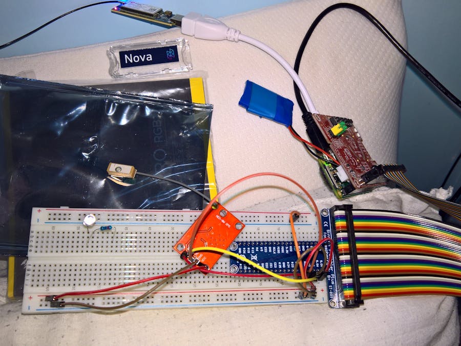
WiringWiring the Raspberry Pi to the UPS PIco and the GPS receiver was a simple task. The UPS PIco is a standard HAT so it simply slots on top of the Raspberry Pi. The GPS receiver requires a bit more effort.
The Neo-6M GPS Receiver which i had chosen for this project has 5 pins on it. These are: VIN, GND, RXD, TXD and PPS. These would all have to be wired to the Raspberry Pi to be used properly. The VIN and GND are simple and was attached to the 5v and Ground lines from the Pi. The RXD and TXD were also simple as these are serial connections and wired to the opposite lines on the Pi (RXD -> TXD and TXD -> RXD). The PPS could be wired to a GPIO pin of my choosing so i chose Pin #18.
The next thing to attach to the Raspberry Pi was the Hologram Nova 3G Modem. This was plugged into the MicroUSB port via a MicroUSB -> USB adapter.
CodingOnce it was all wired it was time for the fun part: writing the code! As i would be using Buildroot to create my OS i had to first setup the environment. Because this project would be open source i threw together a new Git repository on Github and cloned the new blank repo. I then added Buildroot as a new submodule so it was part of my project.
Once it was added, i added some key folders to the root of the project (skel and conf) and hopped into the Buildroot directory to start on the initial configuration. Now, buildroot comes with a bunch of handy things including a defconfig for a Raspberry Pi Zero, this would make life easier as i wouldn't have to do as much manual configuration! So to start i ran the following command:
make raspberrypi0_defconfig
This created a default configuration for the Pi Zero. From here i went in and modified it to my requirements (stripping out unneeded things, tweaking little bits, adding the skel directory i created earlier to the root filesystem overlay). Once Buildroot was configured it was time to configure the Kernel. This is done by running the following
make linux-menuconfig
Once in the kernel configuration i made my own tweaks (removing unused things such as sound and video components, and making other small changes) and added the required components for WiFi as the default config for the Pi Zero does not include the wifi drivers. Wireless on the Raspberry Pi is provided by the same Broadcom chip as the Pi 3 so this was easy to add. (Broadcom 43xx wiress support and Broadcom FullMAC WLAN driver with USB bus interface support).
Once configuration of both Buildroot and the kernel were done, i copied the configuration files to the 'conf/' directory in my main project root so i could add these to the main repository (See https://github.com/VRocker/PiCarTracking/tree/master/conf) and then it was time to run make and wait.
Once buildroot had finished compiling i had a nice little RAM based OS which booted on the Pi but did nothing else. Not very useful! It was now time to look into using the GPS receiver. I could've just used gpsd and bodged it to my requirements but where's the fun in that! It was time to get cracking on the code.
Coding: GPSLoggerMy language of choice is C and C++ while my preferred IDE is Visual Studio (which now has Linux support, yay!) so it was time to create a new project. This daemon would be called GPSLogger and would handle parsing of the GPS data, logging it to a file and passing the parsed coordinates to other services on the device. It would also be responsible for passing the time from the GPS to NTP so the Raspberry Pi could have accurate time, because time is important!
To read the data from the GPS receiver i would need to open a serial port (/dev/ttyS0), parse the data (based on the NMEA protocol) and process it. I wrote a nice little class which would provide an easy way to interface with the serial port called SerialHandler which handled all the setup and safety checks for the port so it wouldn't have to clog my main code up. This class opens a port with a baud rate of 9600, setups up a PPS device (using time_pps_create) and allows reading and writing to the serial port as well as waiting for the PPS.
As one of the GPSLoggers jobs was to pass the lcoation data to other daemons on the device i would have to devise a method for it to do this. The simplest and easiest way i could think of to do this would be to use Shared Memory. The shared memory system in Linux allows multiple applications to share a set chunk of memory where they can bother read and write data at the same time and share between services. I wrote a few helper functions to assist with writing to shared memory as well as a struct to hold the actual data i wanted to pass and placed this in a 'shared' folder in the project root (as it would be shared between daemons). I chose the shared memory address of 0x44495030 as it was not in use on the system and wrote the code to create, cleanup and add data to this memory area (See https://github.com/VRocker/PiCarTracking/blob/master/shared/locationshm.cpp). The data i would be storing in this memory area would be:
- Longitude
- Latitude
- Speed
- Timestamp
The reason i would be storing timestamp is so that other daemons could see how old the data is in the memory block. I didn't want to be sending coordinates if they were 30 minutes old!
Now that i had a shared memory area to store the data, and a serial handler to read and write to the serial port, it was time to actually parse the information given out from the GPS. The way GPS receivers transmit data to the host device is by sending a line of text, starting with $ and ending with a new line (\r\n) with sections of the line being comma separated. This is known as NMEA.
As i couldn't control when the GPS would start sending messages to the device it was possible that when reading i may get partial messages so i figured the best way to read data from the receiver was to read a single byte at a time until a $ was found, then keep reading single bytes until a new line was detected or i ran out of space in the buffer (if this happened then its likely it was a bad message).
Once the data was read from the receiver it was time to parse it. There are many different types of NMEA messages and they're designated by the first chunk of the GPS message ($GPGGA, $GPRMC, etc). A handy site which details the different messages and their structures can be found at http://aprs.gids.nl/nmea/
I went ahead and wrote an NMEAParser class which would parse the relevant information as well as verify the checksum given by the GPS (i didn't want bad data sneaking in there) and wrote a few classes to handle the different messages and save their data. While the NMEA parser was written to handle the 5 different types of messages sent out by the Neo-6M GPS receiver, i was only really interested in the GPRMC message. This message is known for 'Recommended minimum specific GPS/Transit data'. The RMC message holds the date, time, lat, long, speed and heading so it's exactly what i wanted. Parsing the RMC message is simple due to it all being comma separated and following a well known specification so all i had to was was strip the string based on commas and convert the data to their correct data types.
Now the parsers were written it was back to the main loop. I wrote the NMEAParser to return a type of INmeaMessage which the downstream parsers derived from. This class had a field to say what type of mesasge it was so i could check this, recast the pointer to the correct class and read their data fields. A nice little feature of C++ classes. I added a check for the type of the RMC message and made sure the message had a valid fix (The GPRMC message contains a V if the GPS does not yet have a valid lock, or an A if it does).
If the GPS had a valid fix on the satellites it was time to add it to the the shared memory block. Thanks to the earlier locationshm helper i created, this was easy. However, i did have to convert the values returned from the GPS before inserting them into the shared memory block. This is due to the GPRMC message not containing actual Lat and Lon values, and the speed being in Knots. It was time for another helper function to do the conversion for me as i wanted Latitude, Longitude and Speed in Meters. This was named gpsutils and placed in the shared folder. The Lat/Lon contained in the GPRMC message is in the following format: Degrees + Minutes (DDMM.SSSSSS) so, for example, 3137.36664,N would be 31 Degrees, 37 Minutes and 36 seconds in the Northern Hemisphere.
Once all the conversions were done and the data was stored i nthe shared memory block, it was time to get on with another function of the GPSLogger... actually logging to a file. I created yet another helper class for this (i just love my helper classes) and decided to write the data logs to a new folder in the root filesystem named 'gpsdata'. This folder would be mounted to another partition of the SD card so that i would be kept separate from the boot files for safety. The files would (for the moment) store the raw GPRMC line so that it could be downloaded and parsed on another machine at a later date. Later on i may change this to a GPX file or a binary format to save space.
As GPSLogger would already be parsing the NMEA sentences and be receiving the time from the GPS receiver, it would be rude not to utilize this to correct the systems internal clock. To do this i utilized the shared memory system again but this time to interface with the NTP daemon. However, i couldn't just set the shared memory to the date/time whenever i received a GPRMC message as these aren't actually accurate to the second, which would result in NTP being all over the place and rejecting the time that i would be setting... This is where the PPS comes into play!
The PPS output of a GPS receiver stands for 'Pulse-Per-Second'. This does exactly as it says and gives you a pulse every second. However, this pulse is synchronized with the GPS system so that this 1 second pulse is accurate within milliseconds (or sometimes even microseconds) to the GPS satellites in space. This is a very accurate pulse! The pulse alone doesn't tell you the time but the NMEA messages do so you combine the two to get the time accurate to under a millisecond.
To process the PPS event from the GPS, i created a new thread to run alongside the main loop. This was so that the wait for PPS didn't block the main loop so that it could still process other messages while waiting for the 1 second pulse. The code for the thread is show below:
void* ppsThread(void* threadId)
{
	while (g_isRunning)
	{
		if (SerialHandler::GetSingleton()->WaitForPPS())
		{
			if ((g_rmcMessageValid) && (g_rmcMsg))
			{
				// Update the NTP shared memory segment
				NtpUpdater::GetSingleton()->SetNTPTime(g_rmcMsg->Date(), g_rmcMsg->Timestamp());
				g_rmcMessageValid = false;
				delete g_rmcMsg;
				g_rmcMsg = nullptr;
			}
		}
	}
	pthread_exit(0);
}
The way it functions is:
- While the daemon is running (as defined by the variable g_isRunning, which is only ever set to false when the system receives a kill signal)
- Wait for the PPS from the GPS
- Check if the global variable 'g_rmcMessageValid' and 'g_rmcMsg' is set (These are set in the main loop when a valid GPRMC message is received and parsed).
- Prod the NtpUpdated helper class (told you i love helper classes) to update the shared memory block for NTP with the date and time received from the GPS
- Set the 'g_rmcMessageValid' variable to false so we don't get stuck in a loop setting the same thing over and over
- Delete the 'g_rmcMsg' variable as its no longer needed and was allocated elsewhere. Always remember to clean your memory up when you're done with it! It also sets the variable to null after deleting so we don't have a dangling pointer (those things are bad, mmkay).
Now that we're done with setting the location data in the shared memory, logging to file and telling NTP what the current time is, that's the end of GPSLogger, right? Maybe! But there is some extra bits of code in the GPSLogger which isn't just for logging which is worth mentioning.
When GPS receivers start up, they have 3 start up modes. These are:
- Cold Start - When a GPS receiver cold starts, it has no information about the satellite locations, its own location or the current time. Therefore, to get a lock it must search for the satellites and attempt to work out where they are and what the time is (since GPS works on timing but lets not get into that). This can take a long time to get its initial lock.
- Warm Start - In a warm start, the GPS receiver has approximate information for its time and position but doesn't know where the satellites are in the sky. To get this information is has to download some information from the Satellites (The ephemeris data, which can take up to 36 seconds to download) so that it can successfully track the satellites in the sky and give accurate positional data. This data is only valid for 4 hours so the receiver will usually warm start when it's been off for more than 4 hours.
- Hot Start - If the receiver has been off for less than 4 hours it starts in Hot Start mode as the Ephemeris data is still valid. This allows the receiver to get a lock the fastest.
Why am i mentioning this? Several reason really. For starters, this is in a vehicle GPS tracker so it's likely that the power will be off for more than 4 hours while the vehicle is parked, so at the very least it will warm start most of the time. Another reason for mentioning this is that the GPS receiver i have chosen for this project (Neo-6M) does not have a battery attached to it. Usually GPS receivers have a small battery attached to them so they can keep their positional and time data while the power is off. The Neo-6M does not have this so whenever is starts up it usually goes into Cold Start mode. This takes forever to get a lock so we need to help out here...
U-Blox (The chip on the Neo-6M) have a nice way to interface with the GPS chip to configure the chip and, more importantly, give it hints of the time and position data. Infact, U-blox themselves recommend that, upon powerup up, you send the GPS receiving the following data:
- Time, Date and Position (UBX-AID-INI)
- Ephermeris data for where the satellites are in the sky (UBX-AID-EPH)
By sending this data on startup, you can significantly reduce the time to get a lock on the satellites when starting up.
Now, getting back to our GPSLogger process... The functionality was started on to send this data to the GPS chip on startup to help with a lock. However, this is currently not finished as i decided to focus on more important things (such as actually uploading the location data). This will be worked on in the future but the key idea is:
- When starting the GPSLogger process, send the AID_INI and AID_EPH messages to the GPS receiver. These messages will be constructed by reading the last known position and ephemeris data from a file on the SD card
- When the daemon is exiting (after receiving a kill signal), store the positional data and ephermis information from the GPS to the SD card. This is done by sending the AID_INI and AID_EPH messages with no parameters to the GPS receiver and waiting for the response.
As i said, this is currently incomplete but will be worked on. There is currently a helper class for the UBX protocol in the ublox folder fo the gpslogger project folder (https://github.com/VRocker/PiCarTracking/blob/master/gpslogger/ublox/Ublox.cpp)
Coding: CellUploaderSo now we have the location data and speed in the shared memory block but how do we upload that? We need another daemon! This will handle the 3G connection initialization and uploading of the actual data.
A bit of background stuff first though... I am using the Hologram Nova which is a neat little 3G modem designed for projects like mine. One nice thing about it is how easy it is to use and comes with a handy Python SDK to help accelerate projects. Now, this Python SDK would've been useful to me if i hadn't chose the minimal OS approach as my Buildroot-based OS doesn't have Python compiled in. I could've added it but there were a lot of dependencies to go with it so i decided against it. So i made my life harder by not using the Hologram SDK but oh well.
As the Nova is a standard 3G modem, Linux can natively use it as a modem to transmit data but this requires a tiny bit of configuration. To dial a 3G connection on Linux there's several tools you could use but i settled on 'pppd'. This requires a little bit of configuration to be able to establish a connection but this was easily found by reading the Hologram SDK.
2 configuration files are required by pppd to establish a connection. These are: a peer file and a chat file. The peer file tells pppd what it should do with the connection (setup routes, add DNS servers, authentication information) along with the device to use and the data rate. It also defined what 'chat' file to use upon connecting. This is the other type of configuration file. The chat file contains the AT commands to send to the device to establish a connection. Part of these AT command contains the access point name and the number to dial. These 2 configuration files live in the /etc/pppd/ folder in the peers and chat folder.
Another bit of configuration i had to do with pppd was configure the routes for the data. As services such as NTP and SSH were running on the Raspberry Pi, i wanted to restrict what data was sent over the 3G connection and what would only work on WiFi. To do this i settled on not having PPPd setting the default route when establishing the connection and adding static routes for services i wanted to go over the modem. To do this i added an 'ip-up' script to PPPd which is executed whenever a connection is established. These routes currently contain lines to send traffic bound for 10.176.0.0/16 and 10.254.0.0/16 (as these are defined in the Hologram SDK) as well as cloudsocket.hologram.io over the modem connection. These routes will be expanded more as the project grows but for now it's all i need. These configration files were added to the skel folder in the project folder so that they're automatically added to the OS when it's built (See https://github.com/VRocker/PiCarTracking/tree/master/skel/etc/ppp)
Once again, by restricting routes i ensure that only specific traffic goes over the modem, this helps to save data on our sim and cuts down on congestion on the IoT network (although i'm sure Hologram can handle a lot of data just fine!).
So, back to our CellUploader process. One of the things i wanted for this was to make it configurable. This is so the interval in that it reports the current position can be changed without recompiling the entire OS. So it was time to make a configuration helper class! To make things easier i chose a simple KEY=VALUE configuration file and wrote helper functions to read this format. The configuration file would be stored in /picar/etc/picar.conf so it would be separate from the normal system configuration files.
So the first job of the CellUploader process is to load this configuration file. The next job is to connect to the shared memory block that the GPSLogger service is reporting its location data to. If for any reason it fails to connect to this shared memory block, it exits with an error.
Its next task is to dial the PPP connection to establish a connection with Hologram. This is done with the following system call:
/usr/sbin/pppd call hologram.provider
Once it has called this, the process enters a loop checking if ifconfig has an entry for ppp0. This is done to check if a PPP connection has been successfully established and that we have been assigned an IP address, as it would be pointless trying to upload data over the 3g connection if we had no network to upload data over.
Once the connection is established, the CellUploader process starts reading from the configuration file. It first obtains how often it should report the location data by reading the item 'ReportingInterval' from the config. It then reads the 'DeviceKey' from the configuration file so that it can successfully map the Nova to your account on Hologram. If its unable to read the DeviceKey it exits as it wouldn't be able to upload data to Hologram.
The next step is to wait for the GPS to get an initial fix. If the GPS does not have a valid GPS lock then why would we upload positional data? Once the GPS is reporting a valid fix it enters the main loop.
The main loop does a few sanity checks before attempting to upload the positional data. These are:
- Make sure the data has changed since last upload - Why would we upload the same data twice? This is done by checking the timestamp.
- Make sure the GPS data is still valid.
Once these checks have passed, the data is uploaded to the Hologram cloud using the Embedded API (https://hologram.io/docs/reference/cloud/embedded/). This is sent in json format with the device key, Lat, Lon, Speed and a tag to say its location data (Used later by the Hologram routing in the dashboard).
After the data is uploaded, the loop is slept for the amount of seconds defined in the configuration file under 'ReportingInterval' before starting the loop again. The process will continue to do this until it gets a terminate signal. This signal will tell the CellUploader process to upload the coordinates one final time, disconnect the PPP connection and exit.
Coding: UPSPicoThe UPS PIco which i have chosen to keep the device going when the power is lost requires some services running on the device to report its power status as well as how to handle a graceful shutdown. The helpful guys who make this suply a Python SDK to do this but, once again, i'm not using Python on my device so... more hard work!
...or not, because i've used the UPS PIco in other projects before i have already converted their Python SDK to C++ and added it to Github (https://github.com/VRocker/UPSPico) so it was simply a case of adding this project to my Git repository as a submodule. I'll explain how this works though.
When the UPS PIco starts up, it starts monitoring a specific GPIO pin (Pin 22). It does this so that it knows the Raspberry Pi is alive and well. More specifically, it knows that its currently running. This is done so that the UPS PIco knows if its safe to stop supplying power or not when the Pi itself has lost power.
When the UPS PIco detects that the Pi itself has lost power, it starts a countdown timer (which is configurable) and then toggles a GPIO pin (Pin 27) to tell the device to shut down.
The UPSPico service i wrote for the Pi simply toggles Pin 22 every 250ms to tell the UPS that its still alive and listens for pin 27 to be toggled so that it knows to shut down. When pin 27 is toggled it executes '/opt/upspico/shutdown.sh' which tells services to start exiting and finally runs a poweroff.
Putting it all togetherNow comes the part when we put it all together and make it work! It was time to write a few Makefiles to compile the daemons, copy files to their correct locations and compile the OS with the configuration files and daemons built in.
The main Makefile lives in the project root and sets the compilers to use (buildroot creates cross compilers when setting up), directories to use and copy to as well as what projects to compile in. The Makefile can be found here: https://github.com/VRocker/PiCarTracking/blob/master/Makefile
Once built, a zImage is copied to the project root which contains the entire OS and everything needed. At the time of writing this comes out at 17MB. Not bad for a full OS with WiFi!
The next step is actually putting this on an SD card. I decided to create 3 partitions on the SD card for different reasons. The first partition would be the boot partition. This holds the zImage and Raspberry Pi firmware along with the DTBs and config.txt to tell the Pi how to boot. The second partition contains configuration files specific for the Pi. This would be /picar/etc/picar.conf along with the NTP drift file, wifi configuration and any other configuration file that needs to persist between reboots (remember, the OS runs in RAM so any changes go *poof* when powering off). The third partition would be used to store the GPS log files. All 3 partitions would be formatted FAT32 so they can be read by both the Raspberry Pi and any PC that the SD card is plugged in to. FAT32 may not be the best option for the SD card for storing log files so i may change this to F2FS later on so try to prolong the life of the SD card as F2FS is flash-safe (not entirely sure if SD cards benefit from F2FS but I've used it with other projects fine).
So on to copying files. We only need to copy files to the first partition. These files would be the zImage and the Pi firmware. Buildroot automatically pulls down the Pi firmware based on the configuration i gave it earlier and stores it in 'buildroot/output/images/rpi-firmware'. These files were copied to the first partition on the SD card along with the 'bcm2708-rpi-0-w.dtb' file found in the 'buildroot/output/images/' folder. The config.txt also needed changing to setup i2c, OTG on the microUSB and the PPS pin so this was written and stored in the project root as well as copied to the SD card.
Now lets get this show on the road!
First time bootingThe SD card was prepped and inserted into the Raspberry Pi. Everything was wired up and power was given. Lights started flashing to indicate life and the UPSPIco status light slowed from a rapid flashing to a slower flashing to indicate that the UPSPIco service was up and running on the device. The device was alive! Now how would i get to it... It was designed to be headless so there's no console running and i had forgotten to give it the wifi configuration. Damn.
Time to power down the unit (Using the FSSD (File Safe Shut Down) button on the UPSPIco to properly init a shutdown) and remove the SD card. The SD card was placed into my computer and the following file was created on the second partition: 'etc/wpa_supplicant.conf'. This contains the configuration for which WiFi networks the unit should connect to. This is your standard wpa_supplicant file and can be 'borrowed' from any other configured linux machine on the network (and that's exactly what i did).
Take 2. Inserted the SD card and booted her up. She's alive and i can see from my wireless AP that a new device has popped up. It's working! Beers all round! I proceeded to fire up my favourite SSH tool (Putty obviously) and SSH'd in to the unit using the credentials 'root' and 'picar' (set earlier in the Buildroot configuration file).
She's alive and kicking. Running ifconfig confirmed that the connection to hologram had been established and running 'route -n' showed that my custom routes had been applied.
Time to head over to the Hologram Dashboard to check if the data is being reported. It was!
(I blanked out the location in the above screenshot as i don't want anyone turning up at my house... well, not unless you're willing to bring beer)
FittingNow it's all good running on a breadboard in a house but that's not what the project is designed for. The next step in my journey to creating the GPS logger is to actually fit it to the car.
I can't really wedge a breadboard with a bunch of wires under the dashboard of my car so i broke out Fritzing and designed a small PCB to sit on top of the UPSPIco which would allow me to solder the GPS receiver to the PCB and not require any wires which could come loose.
I've not really used Fritzing much so the board is a bit of a mess (and i used Autoroute for the tracks... i know that makes some people puke but it works!) but it does the job. I decided to add some tracks and headers so that i could add an Accelerometer to the board at a later date if needed, so i could also log g-forces along with GPS data. Another function for this would be to potentially detect a collision and force and automatic upload of position with the tag 'collision' so this could be routed properly on the Hologram dashboard.
With the PCB fitted and the GPS soldered, it was time to rip the car apart. The dashboard on my car comes out easily (13 screws - had it out many times for various reason) so this wasn't a problem. The fuse box for my car is also under the dashboard so not much wiring was required. I obtained a fuse splitter thing (allows 2 devices to be run from one fuse slot, provides 2 fuse sockets - 1 for the original fuse and one for the addition, along with a wire to add your new device) and plugged this in to the rear wiper fuse socket as this is only ever live when the ignition is on.
With the fuse split, it was wired up the DC-DC buck converter which was then wired to a MicroUSB cable with the USB-A end chopped off. A bit of soldering and a lot of hot glue later and it was all wired up and secured in place. I then re-fitted the dashboard and it was good to go!
(Sorry no pictures of it actually fitted yet. I was too excited when fitting that i forgot... will take some another day and upload)
Final ThingsNow i have a GPS logger fitted in my car which reports its location whenever the ignition is turned on, turned off and at 5 minute intervals but there's a few small things that need working out.
- I currently can't get the logs off the Pi without SSHing into it (due to how i fitted it) so these need to upload over WiFi when arriving home. This will be done later.
- GPS can take ages to get a lock due to the small antenna supplied with the Neo-6M. I might invest in an active antenna in the future to help with the accuracy and speed of first lock.
- I currently don't have any routes set in the Hologram dashboard for the location data. I'm planning on making a web service to forward these events to at a later date so i can show them on a fancy map.
- I plan to eventually have a way to ask the device for its current position by sending a message via the Hologram cloud. This would interrupt the reporting lop and give the position back straight away. This will probably be done once i have that web service with the fancy map.
I have supplied all the code needed and details here on how i made this so you can go ahead and make your own! Feel free to adapt it to however you like and route the data to wherever you want. There's a few things you'll need to know if you want to create your own PiCarTracker though.
- You'll need a linux PC to compile this. Any architecture will work as Buildroot has cross compilers. Unfortunately you won't be able to use the Windows Subsystem for Linux as it doesn't support fakeroot yet (and that's needed to put the OS together), so fire up your favourite VM if you don't have a physical Linux box lying around.
- After cloning the initial repository and it's submodules, run 'make setup'. This will copy the configuration files for buildroot to the buildroot directory and do it's initial compile. This will give you the cross compilers needed.
- Once 'make setup' has run. Just run 'make' from the project root. It will put everything together to give you the zImage file. You're done with compiling now.
- Create the partitions on an SD card as detailed in the section 'Putting it all together' and copy the files across. Remember to copy 'piconfig.txt' from the project root and name it 'config.txt' on the SD card! Without this you'll have no Nova, no PPS and no UPS PIco.
- Create the folders 'picar/etc/' on the second partition and add a 'picar.conf' file to that folder. Within this config file you'll want to add 'DeviceKey=<key>', replacing <key> with the device key found on the hologram dashboard.
- Add your own wpa_supplicant file to the second partition in an etc folder otherwise no wifi for you!
- Enjoy! And if you're going to use this to track your partners car... you should probably tell them ;)
This is not the end for this project! There's still a lot of work to be done. These are:
- Create a web front end to display the coordinates for the tracker
- Upload the log file to said web server whenever the system has a wifi connection
- Add an accelerometer and a daemon to listen to the information given and add to the log file
- Ability to request a 'current location' over the 3G connection. Needs the web front end.
- Give the GPS some assistance when starting up to get a lock faster. Might utilise the ublox AssistNow functionality which involves downloading assist data over WiFi to help with getting an initial lock.
- Add a better GPS antenna to get a more accurate lock
- Maybe add a Bluetooth GATT server with the location data so any bluetooth devices can use the location data (thinking maybe a custom bluetooth-enabled dashcam here) as the Pi Zero W has a bluetooth chip and it would be a shame to waste it...

Comments