Team Cormic’s IOT project is an automated water transfer system. In its simplest form the project monitors the water level in a fill tank, when called to fill the tank a pump is turned on until the fill tank is full at which point the first pump is turned off and a separate pump is turned on to drain the fill tank, once drained the second pump also turns off.In the hydroponic farming industry, a method of growing is referred to as ebb and flow. This method involves the scheduled filling and draining of a large water tank, called a flood table, in which several plant root balls are submerged. Currently the only method widely used to control the water level is to manually turn on a fill valve until the flood table is full and then to open a drain value to drain the table. Our project seeks to automate this task.Incorporating our product not only saves time and money by removing the need for a person to preform the task, but it saves money by allowing for there cycling of the drained water and allows for more precise water level control.
Due to monetary restrictions in the building of a prototype, the scale of the project was determined by the pumps chosen. For our task, Cobalt Aquatics EXT-800 inline pumps were used. These pumps provide a flow rate of 3.5 gallons per minute at a price of thirty-five dollars. These pumps were designed to integrate with standard half inch vinyl tubing in aquarium applications. We chose to keep our prototype on an appropriate scale to these pumps, so we chose to use five-gallon buckets for our reservoir and fill tank separated by ten feet of half inch vinyl clear tubing as transfer piping. Being able to know the water level of the fill tank is essential to the project. Instead of integrating a preexisting depth sensor our team chose to develop a fill detection sensor which could be used in any size or shape fill tank. Central to the sensor design is the Anndason Plastic Float Switch. Two of these switches were placed in the fill tank,one at the bottom and one near the top, at the fill level. Due to the positioning limitations of the switches and their need to be oriented in a vertical direction, the top switch is mounted upside down relative to the bottom switch. The fill tank will house the electronics for the water level sensing while a separate container will house the pump control electronics. The pumps require 110 volts to function and does not poses an integrated power switch, this meant that in order to control the activation of the pumps we had to use a power relay, specifically the Particle Relay Shield.
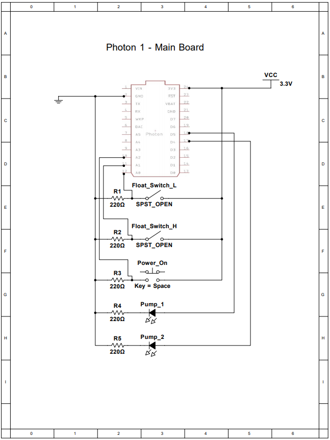
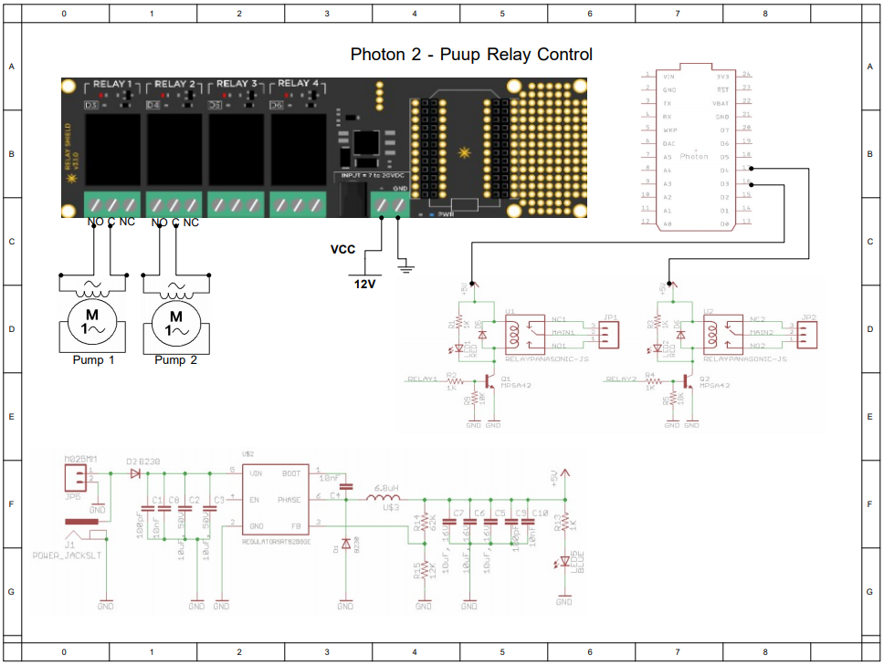
The electrical side of the project was the primary influence on the ability to scale the prototype. This meant that while designing the electrical system it would have to easily integrate with any size fill tank, reservoir, transfer piping,and water pumps. There are two parts to the electrical system, the sensor unit and the pump control unit. The sensor unit involves a circuit which take information from the two float sensors and a start button and relays information to the pump control, it then takes information from the pump control and lights LEDs which correspond to the pump power status for each pump.The start button simply simulates one method for starting the fill sequence, programming in a timer would also work. Controlling the pumps required the use of the relay shield for the photon. The pump cables were cut and wired into the relay board such that the hot wire from the wall was wired into the normally open for each pump and the neutral wires were connected to the common on the relay. This way when the relay is flipped the hot wire is connected and the pump turns on. The circuit diagrams for our project were built in Multi Sim.
Particle Photons were the board used for both the sensor unit and the pump control unit.The programming of the photons was similar but had a few distinct differences.First, on the sensor unit photon, we integrated a sequence variable. This variable was changed depending on the position of the float switches. When the bottom switch was down and the top switch was in the up position, which would be down due to its orientation, the bucket would be in its empty configuration.This is where the program would be started with the push of the start button.This would publish the pump 1 on command to the common file and change the sequence variable to 1. Next when the bottom switch is in the up position and the top switch is in the down position and the sequence variable equals 1, the bucket is full. This would send the switch command to the common file, turning off pump 1 and turning on pump 2 and changing the sequence variable to 2. Now with pump 2 on, the tank is drained. When the bottom switch returns to the bottom position and the top switch returns to the top position and the sequence variable equals 2, the photon sends the pump 2 off command to the common file which turns the second pump off. While this is happening, a separate loop watches for the pump on confirmation commands in the common file from the second photon. When the pump 1 led on command is posted the first photon reads it and turns on the LED indicating pump 1 is on. When the second photon confirms that the first pump is off and the second pump is on, the first photon turns off the LED for pump 1 and turns on the LED for pump 2. Finally, when the second photon gives the all off command, the first photon turns off the pump 2 LED. From the perspective of the pump control photon, the programming is a little simpler. The second photon is watching for the pump commands from the first photon in the common file, when one is posted it preforms the corresponding action and the reports the confirmation of the action back to the common file.
Over all the IOT project provided away for our team to learn and practice several vital roles to modern engineering problem solving. First, we identified a problem which we wanted to solve, then narrowed down the task and simplified the requirements to a more realistic goal. We then designed a physical prototype and an electrical control system which worked together to realize the solution to the problem which we identified. Then figuring out not only how to program the photons but how to program them to do exactly what we wanted them to do. Finally, building the prototype, testing it, and troubleshooting any problems led to a complete prototype which worked as intended. Part of the requirements for the project were to have our photons preform a live update to a spreadsheet. For our task we integrated alive update corresponding to the status of the pumps, we then graphed each pumps cycle separately and calculated the average flow rate and graphed the volume of the fill tank over time. This along with the pump power LEDs are the real time communication display. The project was successful.
Cobalt Aquatics EXT-800 Inline Water Pump
Particle Relay Shield with Photon
Anndason Plastic Float Switch
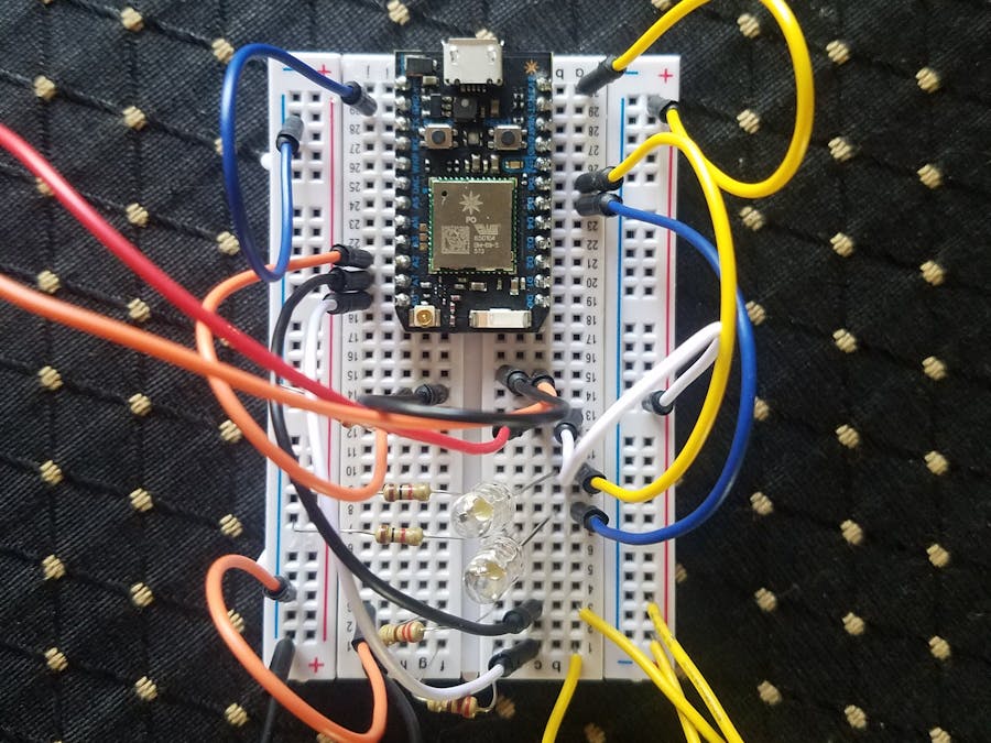
Entire Project Setup Picture 1
Entire Project Setup Picture 2


.png?auto=compress%2Cformat&w=48&h=48&fit=fill&bg=ffffff)


Comments