


Hardware components | ||||||
_ztBMuBhMHo.jpg?auto=compress%2Cformat&w=48&h=48&fit=fill&bg=ffffff) |
| × | 1 | |||
 |
| × | 1 | |||
| × | 4 | ||||
 |
| × | 1 | |||
Software apps and online services | ||||||
 |
| |||||
| ||||||
Hand tools and fabrication machines | ||||||
 |
| |||||
 |
| |||||
 |
| |||||
 |
| |||||
 |
| |||||
Introducing the initiative known as #GestoVoice; Gesture, to Voice Conversion by Riza Mohamed T. This remarkable project was inspired by an encounter with the sister of a deaf grandmother shining a light on the significant communication barriers faced by those who rely on sign language. It underscores the importance of inclusivity and empathetic understanding. Driven by compassion and a relentless desire to empower the hearing impaired this endeavor combines cutting edge technology with warmth to create a solution.
At the core of #GestoVoice lies a blend of state of the art components seamlessly integrated together. The essence of this innovation can be felt through sensors, a coordinating accelerometer, an Arduino microcontroller that showcases computational brilliance and a Bluetooth module for seamless wireless connectivity. These elements harmoniously come together within a glove transforming it into something
Imagine this glove as more than an assembly of parts; it serves as a bridge, between worlds translating gestures into eloquent voices. The journey begins as these gestures flow through the pathways of the Arduino microcontroller, where sophisticated algorithms intricately decode their nuances with remarkable precision to reveal their inherent meanings.
However this transformation is only the beginning.
The infused information soars through the air traveling wirelessly to an Android application where the enchantment intensifies. Within this realm the information undergoes a captivating transformation. Emerges as spoken words.These once-muted gestures are now vocal, articulating thoughts, feelings, and intentions with unparalleled clarity and resonance.
#GestoVoice isn't merely a project; it's a proclamation of progress. It's a testament to the endless possibilities that arise from the confluence of human empathy and cutting-edge technology. With every gesture translated into speech, it dismantles barriers and paves the way for a more inclusive, connected society. The creator's vision is brought to life through #GestoVoice, showcasing not just technical prowess, but also the transformative potential of technology to foster compassion, connection, and positive change.
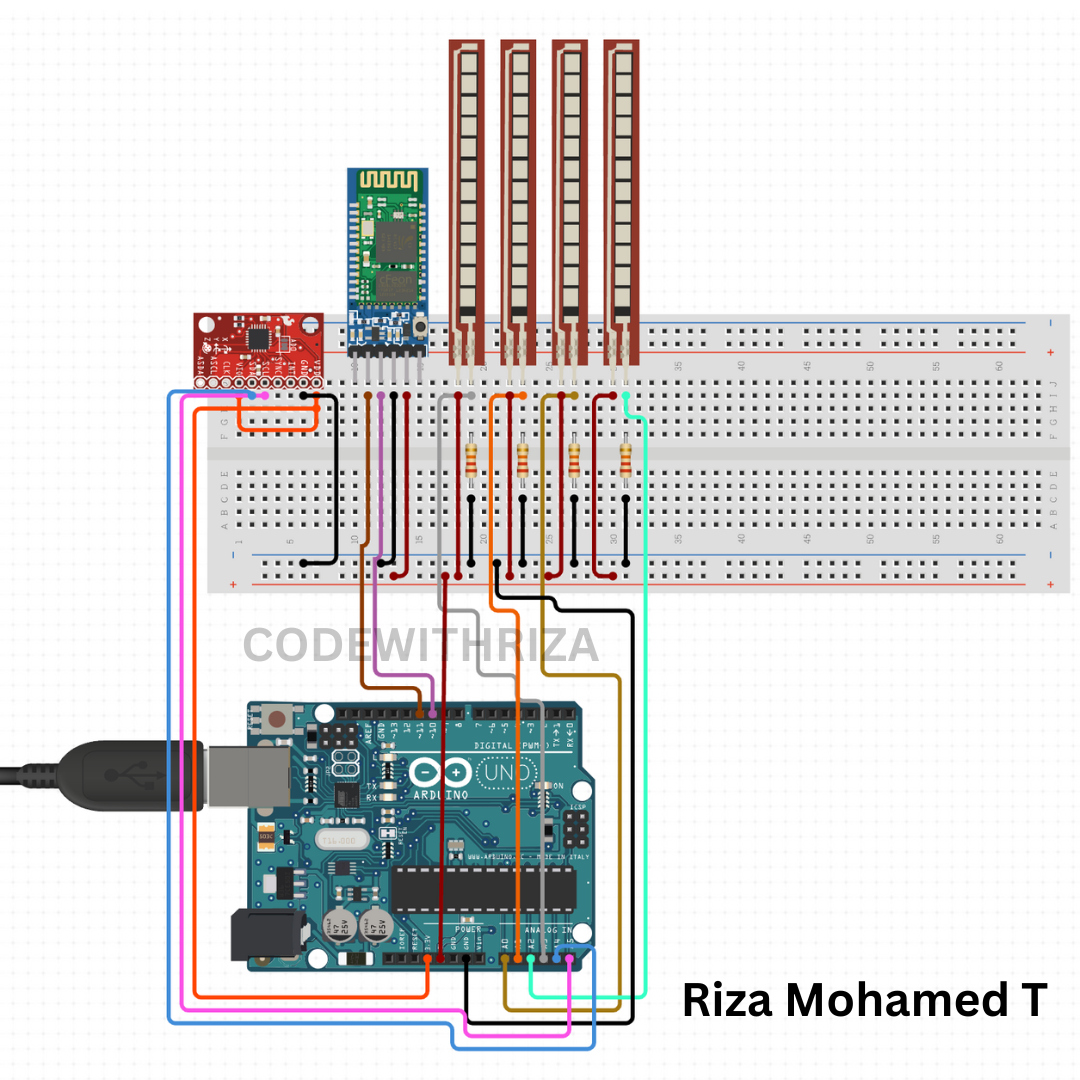
The Circuit Design of GestoVoice
Arduino Board (e.g., Arduino Uno)
Flex Sensors (4)
MPU6050 Accelerometer
Bluetooth Module (HC-05 or HC-06)
LED and Resistor (220Ω)
Jumper Wires
Step-by-Step Guide:
Arduino Setup:
Connect your Arduino board to your computer using a USB cable.
Open the Arduino IDE on your computer.
Connecting Flex Sensors:
Connect one leg of each flex sensor to the 5V pin on the Arduino.
Connect the other leg of each flex sensor to the analog pins (A0, A1, A2, A3) on the Arduino.
Connect a 10kΩ resistor from each flex sensor's leg to the ground (GND) pin on the Arduino.
Connecting MPU6050:
Connect the VCC and GND pins of the MPU6050 to the 5V and GND pins on the Arduino.
Connect the SDA pin of the MPU6050 to the A4 (analog pin 4) on the Arduino.
Connect the SCL pin of the MPU6050 to the A5 (analog pin 5) on the Arduino.
Connecting Bluetooth Module:
Connect the VCC pin of the Bluetooth module to the 5V pin on the Arduino.
Connect the GND pin of the Bluetooth module to the GND pin on the Arduino.
Connect the TXD pin of the Bluetooth module to the RX pin (pin 0) on the Arduino.
Connect the RXD pin of the Bluetooth module to the TX pin (pin 1) on the Arduino.
Connecting LED:
Connect the anode (longer leg) of the LED to pin 13 on the Arduino.
Connect the cathode (shorter leg) of the LED to a 220Ω resistor.
Connect the other end of the resistor to the GND pin on the Arduino.
Uploading the Code:
Copy and paste the provided Arduino code into the Arduino IDE.
Make sure you've selected the correct Arduino board and COM port from the Tools menu.
Click the "Upload" button to upload the code to your Arduino board.
Testing the Circuit:
Once the code is uploaded, open the Serial Monitor in the Arduino IDE.
You should see output indicating the gesture and corresponding spoken response based on the sensor readings.
Bend the flex sensors and tilt the MPU6050 to see how the responses change.


_3u05Tpwasz.png?auto=compress%2Cformat&w=40&h=40&fit=fillmax&bg=fff&dpr=2)

Comments