

_ztBMuBhMHo.jpg?auto=compress%2Cformat&w=48&h=48&fit=fill&bg=ffffff)
This project is a derivative of my "Nipkow Disk Based Digital Display Device" project.
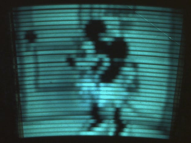
Chall commented "Neat! If you can support 30x30, you could do images. Like they did back in the 30's".
So I wanted to see if this was possible with Arduino.
#include <avr/io.h>
#include <avr/interrupt.h>
#include "Arduino.h"
#include <SPI.h>
#include <SD.h>

// each frame contains 32x64 pixels ( 2048)
// each pixel is represented as one byte in a file on the SDcard. Only the lower 6 bits are used.
// running at 16 frames/s about 32K bytes/s has to be read from the SDcard.
// the SD card can easily do that on average, but some reads take much long than average.
// To overcome this problem two 256 byte buffers are used. When the device is streaming bytes from one buffer the other is being filled from SD card.

#define PinPulse               8  //  IR receiver circuit. (must be connected to  input capture pin 8 )
#define DAC_0LSB               2
#define DAC_1                  3
#define DAC_2                  4
#define DAC_3                  5
#define DAC_4                  6
#define DAC_5                  7

#define SyncPixel              1005 // pixel number that should correspond with synchronisation pulse. Tune this to so that pixel0 corresponds with the upper left corner.
const byte NumberOfPixelBits   = 11;    //  2^NumberOfPixelBits pixels

// global variables used in interrupt routines
volatile unsigned int Pixel = 0x0700;    // current pixel index
volatile unsigned int lastT1capture, Period_Ticks; // used to calculate spinning frequency
volatile unsigned long NextOutputCompare32bit = 0;
volatile unsigned long PixelTime_16bitTickFraction = 1000000000;

volatile char SyncLow=0, SyncHigh =0;
File myFile;
uint8_t buffer[512];
int SubFrame = 0;
long Frame = 0;


void setup()
{
  pinMode(DAC_0LSB, OUTPUT);
  pinMode(DAC_1, OUTPUT);
  pinMode(DAC_2, OUTPUT);
  pinMode(DAC_3, OUTPUT);
  pinMode(DAC_4, OUTPUT);
  pinMode(DAC_5, OUTPUT);
  pinMode(PinPulse, INPUT);  // Configure input capture pin on timer1
  digitalWrite(PinPulse,0);  // floating may have 50 Hz noise on it.
  if (!SD.begin(10)) {
     return;
  }
  myFile = SD.open("mov_26.bin");
  cli();                    //clear interrupts while configuring timer1
  TCCR1A = 0;               //TC1 Control Register A
  TCCR1B = B01000011;       //TC1 Control Register B : free running 250kHz counter, noise canceller enabled, falling edge input capture
  TIMSK1 = B00100010;       //Timer/Counter 1 Interrupt Mask Register: Enable input capture Interupt (ICIE) , Enable Output Compare A Match Interrupt Enable (OCIEA)
  sei();                    // enable interrupts
}

// timer 1 capture interrupt: function is triggered each time the synchronisation hole passes the light sensor.
ISR (TIMER1_CAPT_vect)
{
  unsigned int T1capture = ICR1 ;                    // read timer1 value when the sync occured
  Period_Ticks =  T1capture - lastT1capture;  // period = time between new and previous sync
  if (Period_Ticks > 1000)                    // ignore very short periods
  {
    sei();                              // Increase max pixel clk by enabling nested interrupts (allows COMPA interrupt during sync interrupt)
    lastT1capture = T1capture ;
    signed int SyncError = Pixel - SyncPixel;      // We expect a certain pixel number when sync occurs. Calculate error.
    cli();                              // atomic update of outputcompareStep32bit
                                        // Calculate time between pixels = (time between syncs)/NumberOfPixels + correct part of the error.
                                        // Expressed as 32bit value : 16 bit integer, 16bit fraction -> OutputCompareStep32bit
    PixelTime_16bitTickFraction  = ( ( long)Period_Ticks << (16 - NumberOfPixelBits) ) + ((signed long)SyncError << 6); // each sync a fraction of the error is corrected :
  }
}

// timer 1 output compare A interrupt :function is triggered each time a new pixel should be send to the led
ISR(TIMER1_COMPA_vect)
{
  PORTD = (PORTD & 0x03) | (((buffer[Pixel & 0x01FF]) & 0x3F)<<2); //  write 6 lower buffer values to 6 bit DAC outputs on port D
  OCR1A = (NextOutputCompare32bit >> 16);                          // set new output compare value ( = integer part of OutputCompareStep32bit )
  NextOutputCompare32bit += (PixelTime_16bitTickFraction);         // calculate new output compare value
   if ((Pixel & 0x01FF)==0x00) SyncHigh=1;                          //  trigger to load high bank from SDcard to buffer ( currently reading from low bank )
  if ((Pixel & 0x01FF)==0x0100) SyncLow=1;                         // trigger to load low bank from SDcard to buffer ( currently reading from high bank )
  Pixel++;                                                         // next pixel
  if (Pixel > ((1 << NumberOfPixelBits) - 1)) { Pixel = 0; }
}


void loop() {
if (SyncLow)  { SyncLow=0;  myFile.read(buffer, 256); SubFrame++; }
if (SyncHigh) { SyncHigh=0; myFile.read(buffer+256, 256); SubFrame++;}
if (!myFile.available()) Frame=0;
if (SubFrame>7) { SubFrame=0; myFile.seek(2048*Frame); Frame++;}
}
Compressed folder containing c# project to convert bitmaps to binary
C#Takes N 64x32 pixel bitmap files (frame1.bmp ... frameN.bmp) and converts them to a binary file format read by Arduino
No preview (download only).


Comments