



Hardware components | ||||||
 |
| × | 1 | |||
 |
| × | 1 | |||
 |
| × | 5 | |||
 |
| × | 1 | |||
Software apps and online services | ||||||
 |
| |||||
Hand tools and fabrication machines | ||||||
 |
| |||||
The ESP32-CAM is one of the most popular low-cost development boards for IoT, wireless camera systems, smart home automation, robotics, and embedded vision projects. It combines the powerful ESP32 microcontroller with built-in Wi-Fi, Bluetooth, and camera support, making it an excellent choice for both beginners and experienced developers.
In this guide, you'll learn how to set up the ESP32-CAM, connect it to an FTDI programmer, configure Arduino IDE, understand the pinout, upload your first program, and troubleshoot common issues.
What You'll LearnBy following this guide, you'll learn how to:
- Understand the ESP32-CAM hardware
- Identify all important GPIO pins
- Wire the ESP32-CAM with an FTDI USB-to-TTL adapter
- Configure Arduino IDE correctly
- Upload your first sketch
- Run the Camera Web Server example
- Solve common upload and camera errors
- Explore practical project ideas
The following hardware is used in this guide:
- ESP32-CAM (AI Thinker)
- OV2640 Camera Module
- FTDI USB-to-TTL Programmer
- Female-to-Female Jumper Wires
- USB Cable
- Optional MicroSD Card
The ESP32-CAM integrates an ESP32 microcontroller with an OV2640 camera interface, allowing image capture, Wi-Fi streaming, and Bluetooth communication in a compact and affordable module.
Common applications include:
- Wireless security cameras
- Smart doorbells
- Face detection experiments
- QR code scanners
- Robot vision
- IoT monitoring
- Time-lapse photography
- Home automation
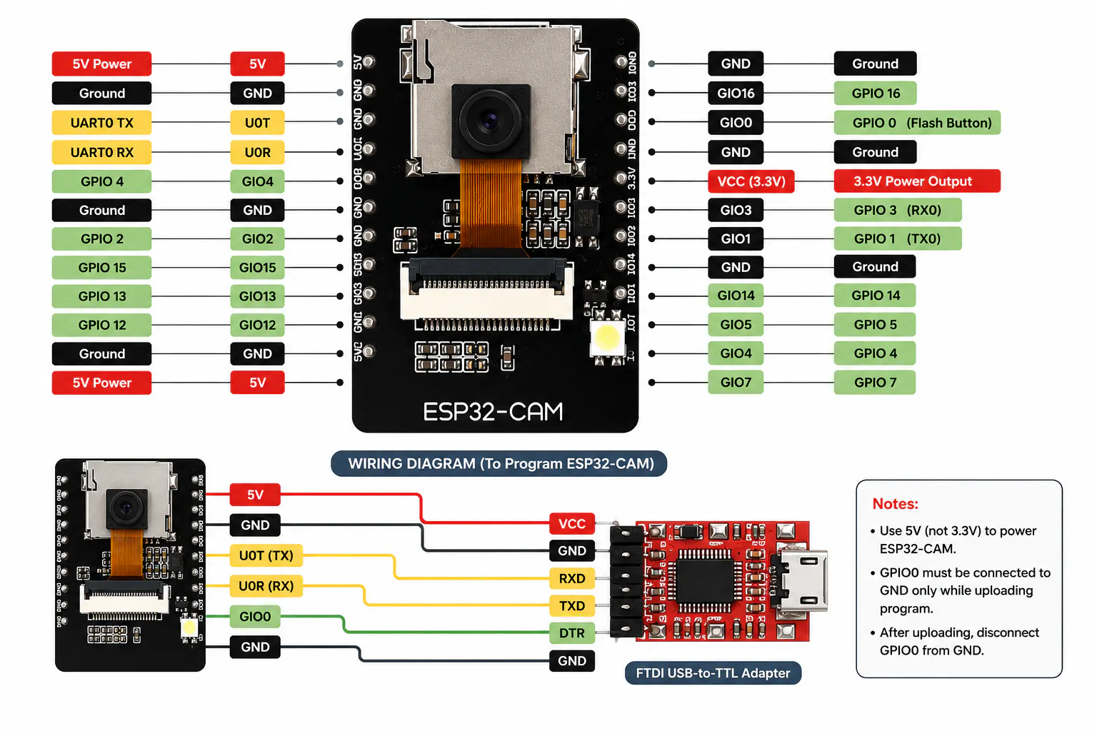
The ESP32-CAM exposes several GPIO pins for communication and peripheral interfacing. During programming, GPIO0 must be connected to GND to enter download mode.
The included pinout diagram shows every important connection and GPIO function.
Since the ESP32-CAM does not include a built-in USB interface, programming requires an external FTDI USB-to-TTL converter.
Programming connections:
- FTDI 5V → ESP32-CAM 5V
- FTDI GND → ESP32-CAM GND
- FTDI TX → ESP32-CAM U0R (RX)
- FTDI RX → ESP32-CAM U0T (TX)
- GPIO0 → GND (during uploading only)
After uploading, disconnect GPIO0 from GND and reset the board.
Arduino IDE SetupInstall the ESP32 board package using the Arduino Boards Manager and select:
AI Thinker ESP32-CAM
Recommended starting configuration:
- Upload Speed: 115200
- Flash Frequency: 40 MHz
- Partition Scheme: Huge APP
Once configured, upload the Camera Web Server example included with the ESP32 board package.
Common ProblemsIf you experience issues, check the following:
- GPIO0 connected correctly
- TX/RX not reversed
- Stable 5V power supply
- Correct COM port selected
- Camera ribbon cable inserted correctly
- Correct board selected in Arduino IDE
Most upload failures are caused by wiring mistakes or unstable power.
Project IdeasAfter completing the setup, you can build many exciting projects such as:
- Wi-Fi Security Camera
- Smart Doorbell
- Motion Detection Camera
- QR Code Scanner
- Robot Camera
- Remote Monitoring System
- Time-Lapse Camera
- IoT Image Logger
The ESP32-CAM is one of the best low-cost development boards for camera-based IoT projects. With built-in Wi-Fi, Bluetooth, camera support, and Arduino compatibility, it offers an excellent platform for learning embedded systems and developing practical wireless applications.
Whether you're building a security camera, robotics project, or smart home device, the ESP32-CAM provides outstanding functionality at an affordable price.
About CHIP.PKThis guide was created by CHIP.PK, Pakistan's electronics marketplace for Arduino, ESP32, Raspberry Pi, robotics, IoT modules, sensors, development boards, and embedded systems.
Explore our Blogs here


Comments